Methods for characterizing subsurface volatile contaminants using in-situ sensors

a volatile contaminants and insitu sensor technology, applied in the direction of mechanical means, process and machine control, specific gravity measurement, etc., can solve the problems of inability to accurately characterize the integrity of off-site analysis of contaminated samples, limited sampling and analytical techniques, and high cost of current methods

Active Publication Date: 2006-02-21
SANDIA NAT LAB
View PDF8 Cites 80 Cited by
  • Summary
  • Abstract
  • Description
  • Claims
  • Application Information

AI Technical Summary

Benefits of technology

[0031]An inverse analysis method for characterizing diffusion of vapor from an underground source of volatile contaminant using data taken by an in-situ sensor. The method uses one-dimensional solutions to the diffusion equation in Cartesion, cylindrical, or spherical coordinates for isotropic and homogenous media. If the effective vapor diffusion coefficient is known, then the distance from the source to the in-situ sensor can be estimated by comparing the shape of the pre

Problems solved by technology

Current methods are costly and time-intensive, and limitations in sampling and analytical techniques exist.
Another problem with current techniques is that the integrity of off-site analyses of contaminated samples can be compromised during sample collection, transport, and storage.
However, while technology exists to detect and analyze VOCs, very few systems are rugged enough to be deployed in-situ (e.g., in soil and water) while providing real-time, continuous, and reliable long-term monitoring.
Many of these devices include sensitive electronic components (which can be damaged by lightening-induced ground currents) and require the flow of an inert carrier gas during operation (i.e., to carry the contaminant vapor up to a chemical analysis unit located on the surface), which may not be amenable to long-term in-situ monitoring and remediation applications.
The probe's housing is not waterproof and, hence, cannot be placed in liquid-saturated soil, water, or other liquids contaminated with VOCs.
However, the Geoprobe Membrane Interface Probe does not perform in-situ sensing or analysis, because sensing is performed by a remote detector/analysis unit located on the surface.
The Cyranose sensor unit, however, cannot be submerged in water for in-situ monitoring because the housing is not waterproof.
Chemiresistors generally should not be placed in direct contact with liquid VOCs

Method used


Image

  • Methods for characterizing subsurface volatile contaminants using in-situ sensors
  • Methods for characterizing subsurface volatile contaminants using in-situ sensors
  • Methods for characterizing subsurface volatile contaminants using in-situ sensors

Examples


Embodiment Construction

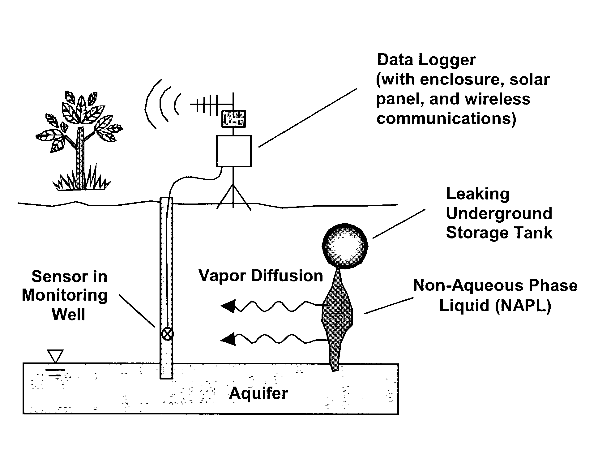
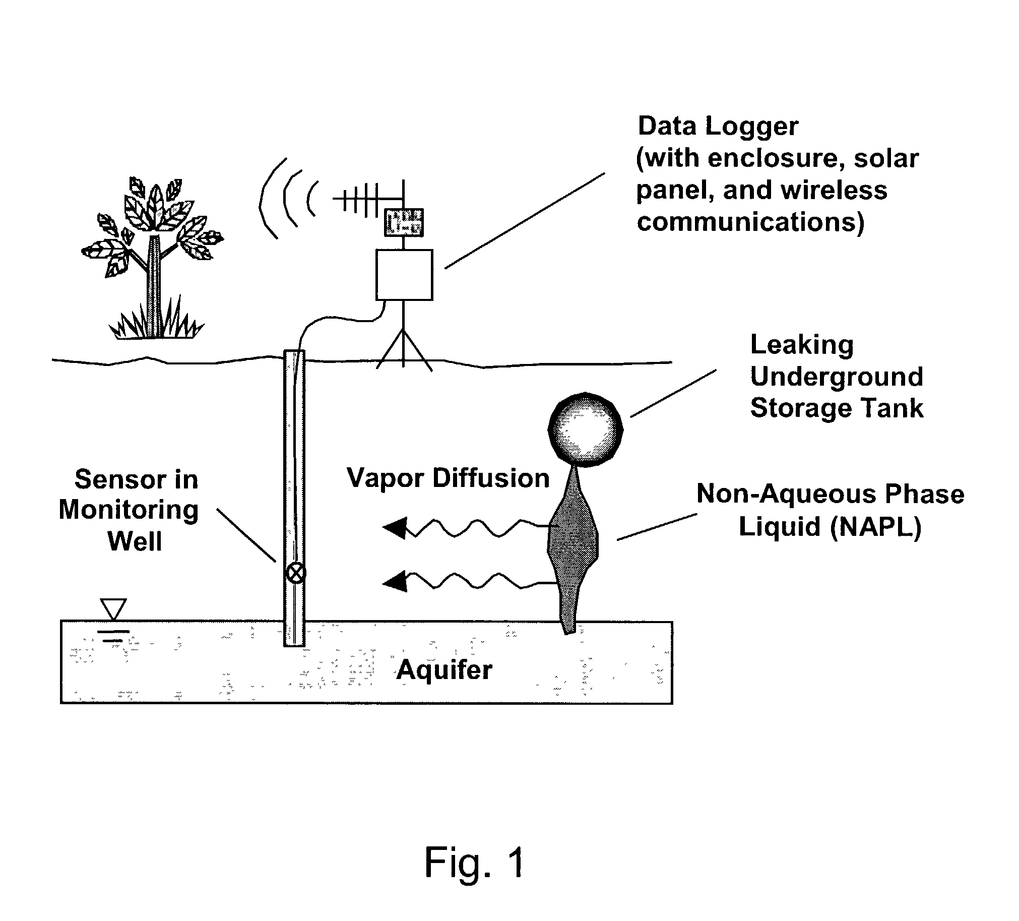
[0041]The present invention relates to an integrated system for performing in-situ monitoring, characterization, and automated, remediation of subsurface volatile contaminants in an optimal and cost-effective way. The present invention also relates to an in-situ, real-time waterproof in-situ microsensor that detects and quantitatively characterizes volatile organic and inorganic compounds in soil, wells, or groundwater. The words “vapor” and “gas” are used interchangeably herein. Similarly, the acronym VOC, which stands for Volatile Organic Compound, is intended herein to also encompass all inorganic volatile compounds (VCs) and other solvents, such as toxic chemicals, explosives, organic compounds having low volatility, and toxic gases.

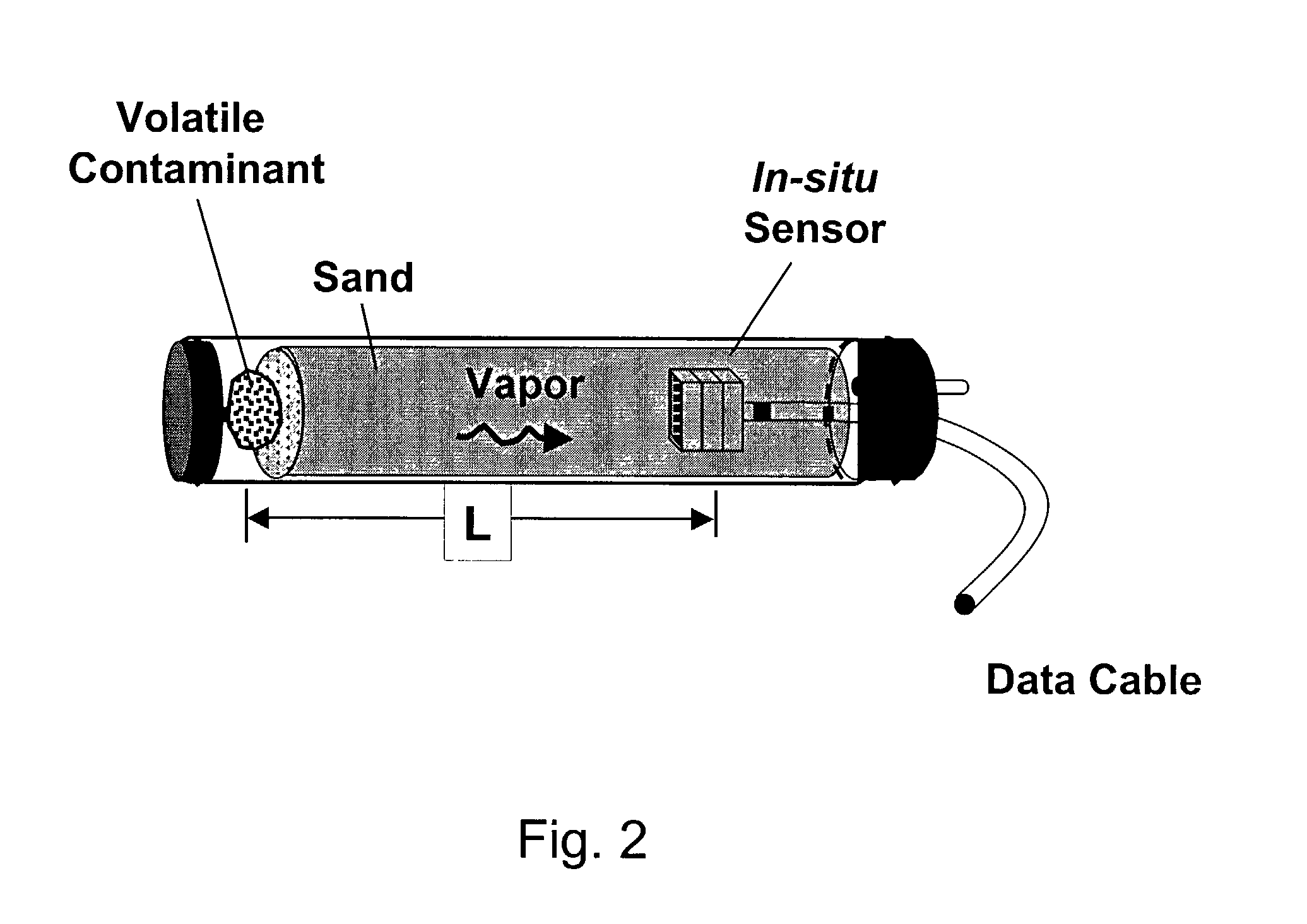
[0042]The terms “in-situ sensor” and “in-situ microsensor” are equivalent, and refer to any robust, rugged, and reliable chemical sensing device that can be emplaced subsurface (e.g., in a well or in direct contact with soil) and can measure in real-...


PUM


Abstract

An inverse analysis method for characterizing diffusion of vapor from an underground source of volatile contaminant using data taken by an in-situ sensor. The method uses one-dimensional solutions to the diffusion equation in Cartesian, cylindrical, or spherical coordinates for isotropic and homogenous media. If the effective vapor diffusion coefficient is known, then the distance from the source to the in-situ sensor can be estimated by comparing the shape of the predicted time-dependent vapor concentration response curve to the measured response curve. Alternatively, if the source distance is known, then the effective vapor diffusion coefficient can be estimated using the same inverse analysis method. A triangulation technique can be used with multiple sensors to locate the source in two or three dimensions. The in-situ sensor can contain one or more chemiresistor elements housed in a waterproof enclosure with a gas permeable membrane.

Description

CROSS-REFERENCE TO RELATED APPLICATIONS[0001]This application is a continuation-in-part of U.S. application Ser. No. 10 / 152,597 filed May 22, 2002, “Waterproof Microsensor for In-Situ Monitoring of Volatile Compounds”, by Clifford K. Ho, et al., which is incorporated herein by reference. This application claims the benefit of U.S. Provisional application Ser. No. 60 / 335,644 filed Oct. 25, 2001, “Characterization Methods for Real-Time In-Situ Sensing of Volatile Contaminants”, by Clifford K. Ho, which is incorporated herein by reference. This application also claims the benefit of U.S. Provisional application Ser. No. 60 / 351,526 filed Jan. 24, 2002, “Automated Monitoring and Remediation System for Volatile Subsurface Contaminants”, by Clifford K. Ho, which is incorporated herein by reference. This application is related to co-pending application by Clifford K. Ho, “Automated Monitoring and Remediation System for Volatile Subsurface Contaminants Using In-Situ Sensors”. This applicatio...

Claims


Application Information

Patent Timeline
IPC IPC(8): G01N31/00G01V1/40G01V3/00G01V3/18G06F19/00
CPCG01V9/007Y10T436/212Y10T436/21Y10T436/214Y10T436/11
Inventor HO, CLIFFORD K.
Owner SANDIA NAT LAB
Why Eureka
Try Eureka