Temperature detection cell, and method to determine the detection threshold of such a cell

a technology of temperature detection cell and detection threshold, which is applied in the direction of instruments, heat measurement, calorimeters, etc., can solve the problems of variation of detection threshold from one to the other, increase in general accumulation, and increase in the temperature of the detection threshold, so as to improve the accuracy of the detection threshold temperature

Active Publication Date: 2006-02-21
ST ERICSSON SA
View PDF9 Cites 4 Cited by
  • Summary
  • Abstract
  • Description
  • Claims
  • Application Information

AI Technical Summary

Benefits of technology

[0018]More specifically, according to the invention, the detection threshold may be computed from measurements of the increasing voltage and the decreasing voltage (VBEON0) at ambient temperature. It is thus no longer necessary to test the cell at high temperature (with a threshold of about 100 to 200° C.). Measurements at ambient temperature are sufficient. The cells can thus be tested at low cost.
[0026]Preferably, the test step is repeated for each cell of the series of cells. The resetting step can then be performed only once before the test steps. Thus, limits are placed on the number of steps to be performed when several cells have to be tested in succession. The resetting step can also be repeated before each test step. Thus, as shall be seen more clearly below, the precision of the value of the detected threshold temperature is improved.

Problems solved by technology

The use of such cells makes it possible to stop the operation, and therefore, the heating of the integrated circuit before it is damaged as a result of the heat.
One problem with present-day detection cells is the variation of the detection threshold from one cell to another.
These errors generally accumulate and finally have a considerable influence on the value of the detection threshold of the cell.
It is noted that for a series of cells sized to have a given theoretical detection threshold TD, it is possible to have cells whose real detection threshold diverges by 20% to 30% from the desired value, which is unacceptable for certain applications.
This does not guarantee that the detection threshold of the cell is taken individually.

Method used


Image

  • Temperature detection cell, and method to determine the detection threshold of such a cell
  • Temperature detection cell, and method to determine the detection threshold of such a cell
  • Temperature detection cell, and method to determine the detection threshold of such a cell

Examples


Embodiment Construction

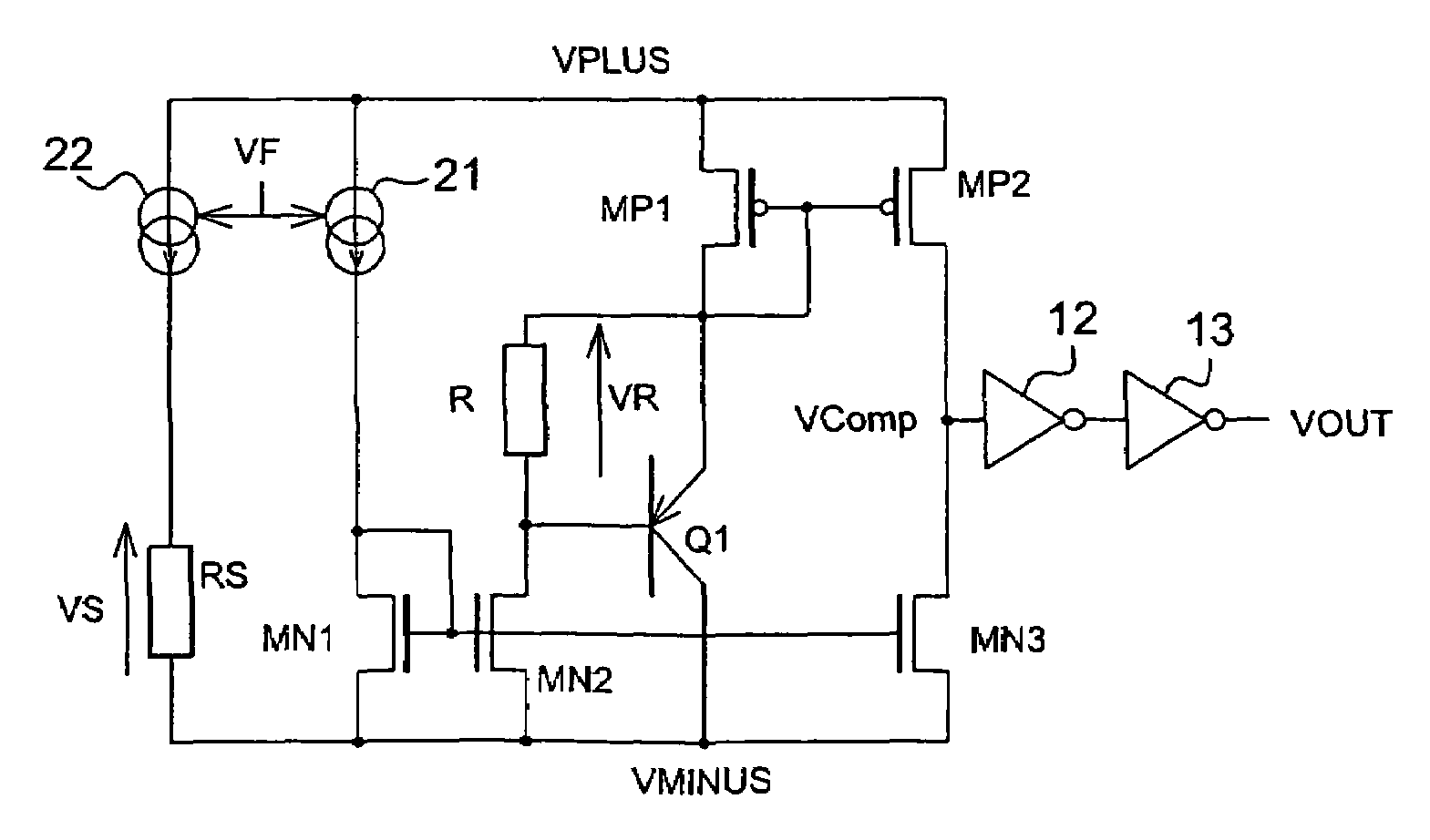
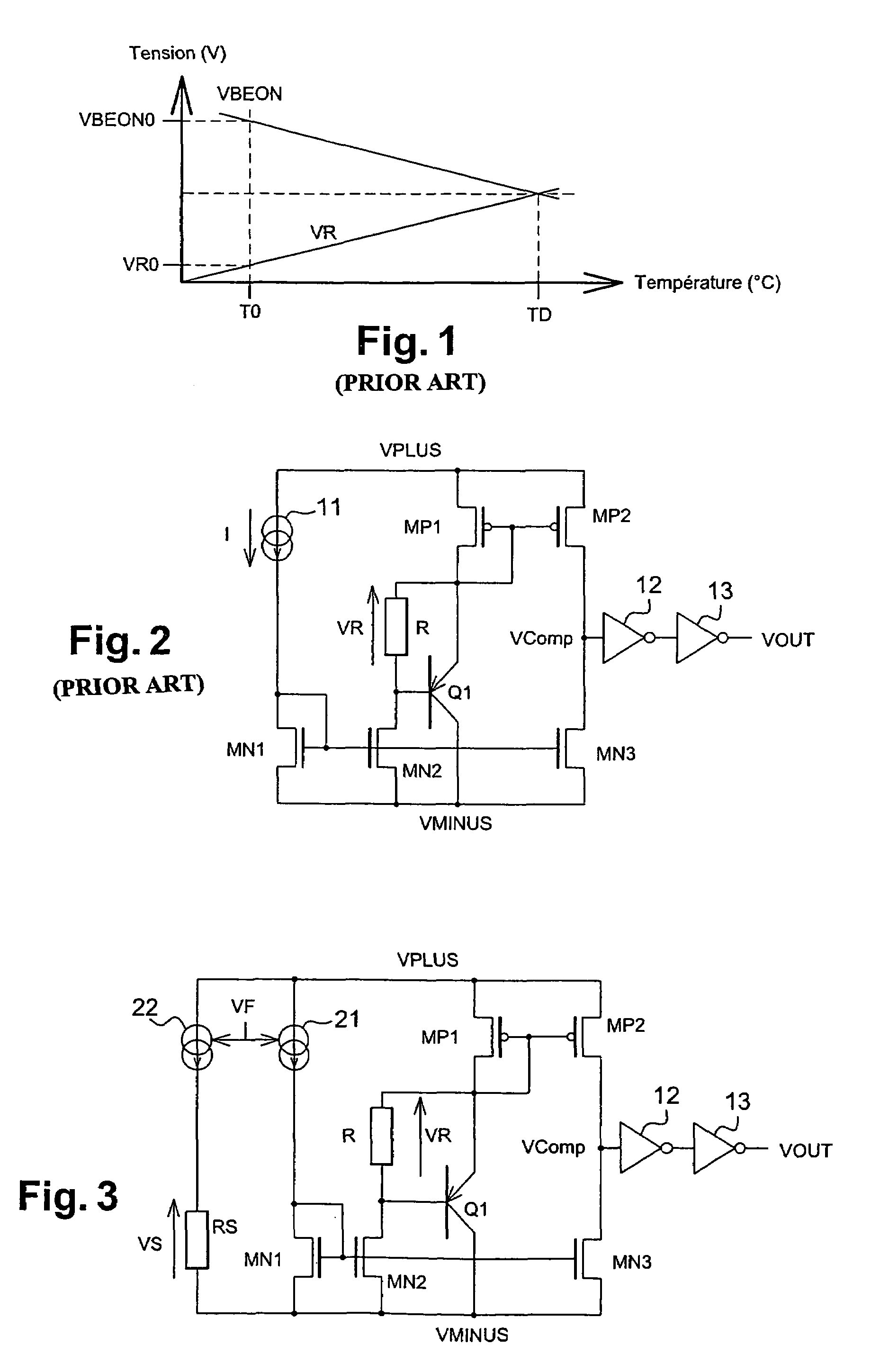
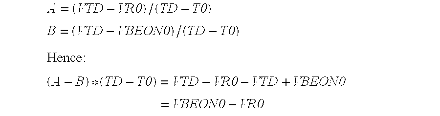
[0032]To obtain a detection cell according to the invention (FIG. 3), a prior art cell (FIG. 2) was modified as follows. The current source 11 was replaced by a current source 21 made according to a scheme similar to the one used for the source 11 of the prior art cell. As compared with the source 11, the source 21 can be controlled by a potential VF. The source 21 produces a current I which is 1) increasing linearly as a function of the temperature for a given value VF0 of the potential VF, and 2) variable as a function of the potential VF for a given value T0 of the temperature T.

[0033]Furthermore, a second current source 22 and a resistor RS connected in series have been added. The potential VPLUS is applied to a terminal of the source 22 having its other terminal connected to a terminal of the resistor RS. The ground potential VMINUS is applied to the other terminal of the resistor RS. The source 22 is identical to the source 21. In particular, it produces a current I that progr...


PUM

PropertyMeasurementUnit
detection thresholdaaaaaaaaaa
temperatureaaaaaaaaaa

Abstract

A temperature detection cell includes a circuit for producing a voltage that increases with temperature, a circuit producing a voltage that decreases with temperature, and a comparison circuit to compare the increasing voltage with the decreasing voltage. The comparison circuit produces a warning signal when the temperature reaches a detection threshold such that the decreasing voltage becomes lower than the increasing voltage. The cell also has a test circuit to determine the detection threshold of the cell. Also disclosed is a method for testing a temperature detection cell, during which the detection threshold of a cell is determined from measurements of the increasing voltage and the decreasing voltage at a reference temperature.

Description

FIELD OF THE INVENTION[0001]The invention relates to a temperature detection cell for an integrated circuit, and an associated method for determining the real detection threshold of such a cell. The invention is used, for example, in integrated circuits for cell phones. It can also be used more generally in any integrated circuit that dissipates heat.BACKGROUND OF THE INVENTION[0002]Temperature detection cells are generally used in integrated circuits as alarms to indicate an abnormal heating of these integrated circuits. The use of such cells makes it possible to stop the operation, and therefore, the heating of the integrated circuit before it is damaged as a result of the heat.[0003]The principle of operation of such a cell is summarized in FIG. 1. The cell has a circuit producing a voltage VR that increases with the temperature T, and is compared with a voltage VBEON that diminishes with the temperature T. At ambient temperature T0, VBEON is higher than VR. When the temperature ...

Claims


Application Information

Patent Timeline
Patent Type & Authority Patents(United States)
IPC IPC(8): G01K1/00G01K3/00G01K7/01
CPCG01K7/01G01K3/005
Inventor RAVATIN, FRANCOISVERA, CHARLESCIOCI, MARCO
Owner ST ERICSSON SA
Why Eureka
Try Eureka