

Control forwarding in a pipeline digital processor
a digital processor and control forwarding technology, applied in the direction of program control, computation using denominational number representation, instruments, etc., can solve the problem of requiring at least one delay cycl
- Summary
- Abstract
- Description
- Claims
- Application Information
AI Technical Summary
Benefits of technology
Problems solved by technology
Method used
Image

Examples
Embodiment Construction
[0025]Before proceeding to a discussion of an embodiment of the invention, an explanation of the terminology used will aid in understanding following description of the invention. First, branch instructions are followed by either the “target” instruction, if the branch is taken, or the “next inline” instruction if the branch is not taken. Second, a branch instruction will either be a “simple” branch instruction or a “complex” branch instruction. Simple branch instructions are those in which the decision of the branch will depend upon some condition that has either been previously determined (e.g., by a compare instruction), is implicit in the branch instruction (e.g., an unconditional branch). A complex branch instruction is one in which the branch decision is made during execution of the branch instruction (e.g., the compare operation is part of the branch instruction) With this terminology in mind an embodiment of the invention can now be described.
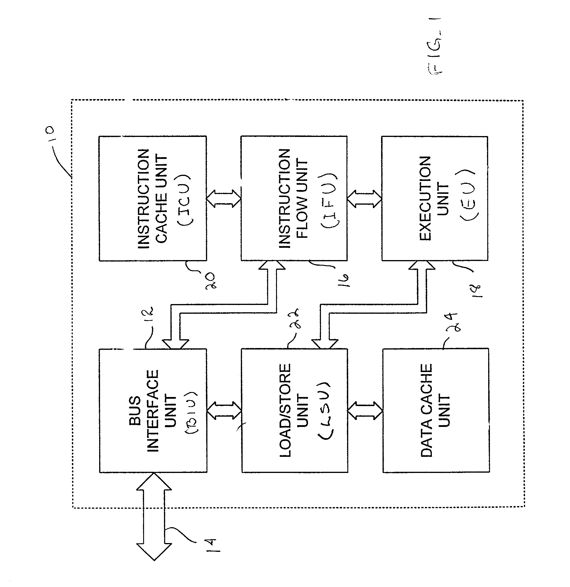
[0026]Turning now to FIG. 1, the...
PUM
 Abstract
Description
Claims
Application Information