Computing device to generate even heating in exhaust system

a technology of exhaust system and computing device, which is applied in the direction of mechanical equipment, machines/engines, electric control, etc., can solve the problems of large portion of the heat generated in the rearward section of the catalyst simply lost through the exit of the device, and devices can become contaminated with sulfates, etc., to achieve accurate control and high modulation frequency

Active Publication Date: 2006-02-28
FORD MOTOR CO +1
View PDF35 Cites 18 Cited by
  • Summary
  • Abstract
  • Description
  • Claims
  • Application Information

AI Technical Summary

Benefits of technology

[0012]By operating the system in this way, it is possible to generate a more even temperature distribution when heating the emission control device to remove sulfur, or during any such heating. This is because the heat is generated toward the front portion of the device, and the exhaust gas flow carries this heat toward to rest of the device. Further, since only a portion of the device is filled and purged with oxidants and reductants, a higher modulation frequency is possible, thereby allowing accurate control at high temperatures even though less of the catalyst storage is being used to generate an exothermic reaction.

Problems solved by technology

However, these devices can become contaminated with sulfates, for example.
The inventors herein have recognized a disadvantage with such an approach.
In particular, when the device is completely filled and then completely purged of stored oxidants, a large portion of the heat generated in the rearward section of the catalyst is simply lost through the exit of the device via the exhaust flow.
This creates an uneven temperature profile in the device, resulting in uneven catalyst degradation and uneven sulfur removal.
Furthermore, such an approach requires a significant breakthrough of reductants (to be detected by the downstream sensor), thereby resulting in potentially increased emissions.

Method used


Image

  • Computing device to generate even heating in exhaust system
  • Computing device to generate even heating in exhaust system
  • Computing device to generate even heating in exhaust system

Examples


Embodiment Construction

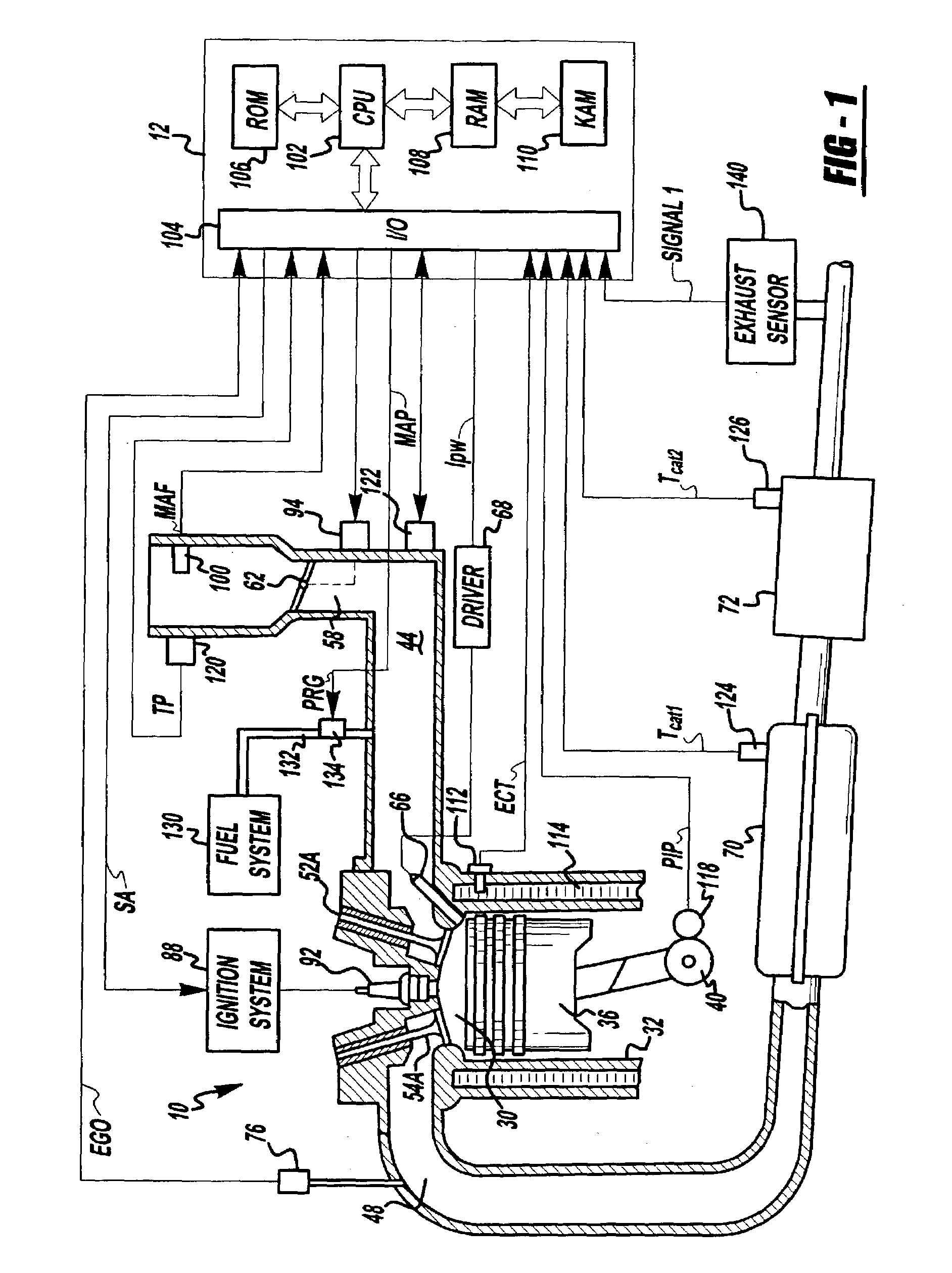
[0028]Direct injection spark ignited internal combustion engine 10, comprising a plurality of combustion chambers, is controlled by electronic engine controller 12 as shown in FIG. 1. Combustion chamber 30 of engine 10 includes combustion chamber walls 32 with piston 36 positioned therein and connected to crankshaft 40. In this particular example, piston 30 includes a recess or bowl (not shown) to help in forming stratified charges of air and fuel. Combustion chamber 30 is shown communicating with intake manifold 44 and exhaust manifold 48 via respective intake valves 52a and 52b (not shown), and exhaust valves 54a and 54b (not shown). Fuel injector 66 is shown directly coupled to combustion chamber 30 for delivering liquid fuel directly therein in proportion to the pulse width of signal fpw received from controller 12 via conventional electronic driver 68. Fuel is delivered to fuel injector 66 by a conventional high pressure fuel system (not shown) including a fuel tank, fuel pumps...


PUM


Abstract

A microprocessor-based controller is provided for generated heat in at various locations in an exhaust system of an engine by changing the heat generation technique utilized. In one case, some cylinder air-fuel ratios are modulated between stoichiometry and rich, while others are modulated between stoichiometry and lean. Another approach operates some cylinder lean, while others are modulated between a first rich, and a second, less rich, value. Further, compensation based on engine airflow is also provided. Finally, various methods are described for temperature control and for controlling modulation of air-fuel ratio.

Description

BACKGROUND OF THE INVENTION[0001]Engines can be coupled to emission control devices, such as catalytic converters, to reduce exhaust emissions. However, these devices can become contaminated with sulfates, for example. In order to remove these contaminates, the temperature of the emission control device is raised significantly and a near stoichiometric air-fuel ratio is provided that alternates, or oscillates, around stoichiometry (between lean and rich).[0002]One type of engine exhaust system routes all of the engine cylinders into a single exhaust path. One approach for raising temperature of such an exhaust path sequentially operates some cylinders lean, and then some rich. Such an approach is described in DE 19923481, for example. In such an approach, the ending of both the lean and rich mixture air-fuel ratio is controlled via a sensor downstream of the device.[0003]The inventors herein have recognized a disadvantage with such an approach. In particular, when the device is comp...

Claims


Application Information

Patent Timeline
Patent Type & Authority Patents(United States)
IPC IPC(8): F01N3/00F01N3/08F01N13/02F01N13/04F02D41/00F02D41/02F02D41/14F02D41/34
CPCF01N3/0814F01N13/011F02D41/0082F02D41/0245F02D41/0295F02D41/1475F01N13/0097F01N13/0093F01N13/009F01N3/0842F01N13/107F02D41/1408F02D41/1441F02D41/187F02D2200/0404F02D2200/0406F02D2200/0802F02D2200/0814Y02T10/26Y02T10/12
Inventor SURNILLA, GOPICHANDRAELWART, SHANE
Owner FORD MOTOR CO
Why Eureka
Try Eureka