MEMS infrared light source and manufacturing method thereof

An infrared light source and infrared technology, applied in the field of infrared light source, to achieve the effects of improving manufacturing pass rate and reliability, reducing thermal mass, and high infrared emission capability

Pending Publication Date: 2022-03-29
JIANGSU UNIV
View PDF0 Cites 3 Cited by
  • Summary
  • Abstract
  • Description
  • Claims
  • Application Information

AI Technical Summary

Problems solved by technology

Solve the above two problems existing in the existing MEMS infrared light source

Method used


Image

  • MEMS infrared light source and manufacturing method thereof
  • MEMS infrared light source and manufacturing method thereof
  • MEMS infrared light source and manufacturing method thereof

Examples


Embodiment 1

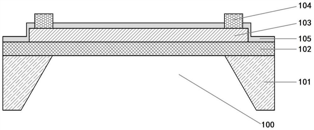
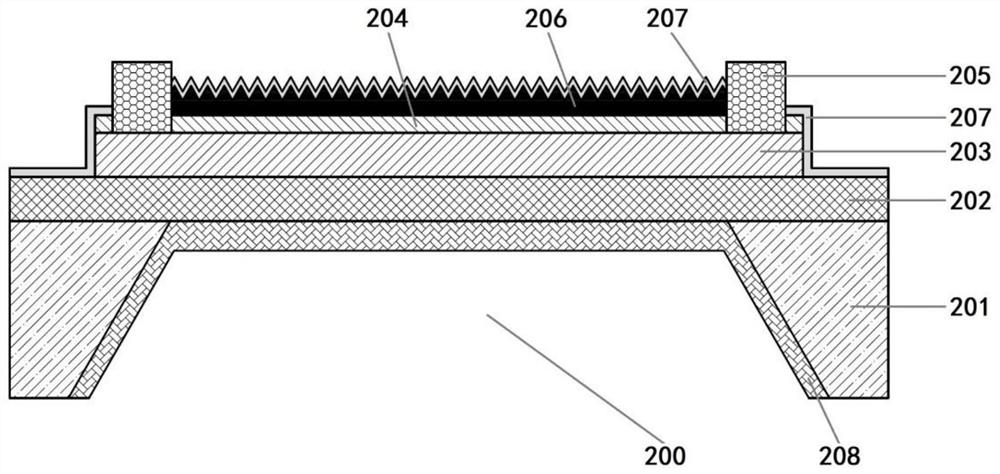
[0048] Such as figure 2 Shown is a schematic cross-sectional view of a MEMS infrared light source of the present invention, including a substrate 201, a supporting film layer 202, a heating electrode layer 203, an isolation layer 204, a heating electrode pad 205, an infrared emitting layer 206, a protective layer 207 and a reflective layer 208 , it is characterized in that: the substrate 201 includes a cavity structure 200, the support film layer 202 is arranged on the substrate 201 with a cavity structure, and forms a four-sided fixed-branch structure connection with the substrate 201, and in the cavity A suspension area is formed above the structure 200, a heating electrode layer 203 is provided above the supporting film layer 202, and heating electrode pads 205 are provided on both sides of the heating electrode layer 203 outside the suspension area, and the heating electrode pads 205 and The heating electrode layer 203 forms an electrical connection, an isolation layer 20...


PUM

PropertyMeasurementUnit
thicknessaaaaaaaaaa
thicknessaaaaaaaaaa

Abstract

The invention belongs to the field of infrared light sources, and particularly relates to an MEMS infrared light source and a manufacturing method thereof. According to the MEMS infrared light source, a reflecting layer with high reflectivity to infrared radiation is introduced into a heating electrode layer and the back of a supporting material (located in a cavity area of a substrate), so that infrared radiation energy radiated by the heating electrode layer to the cavity part of the substrate through a supporting film is reflected back and is radiated upwards through the heating electrode layer; infrared radiation energy capable of being utilized by the infrared sensor is enhanced, the photoelectric conversion efficiency of the MEMS infrared light source is greatly improved, and the heating power consumption is reduced; meanwhile, the ultrathin (the thickness is not greater than 1 micron) infrared emission layer is introduced, so that the thermal quality of the heating electrode layer is greatly reduced while the high infrared emission capability of the MEMS infrared light source is ensured, the modulation frequency of the MEMS infrared light source is improved, and the heating power consumption is further reduced.

Description

technical field [0001] The invention belongs to the field of infrared light sources, in particular to a MEMS infrared light source and a manufacturing method thereof. Background technique [0002] Infrared sensing technology has been widely used in air quality detection, temperature monitoring, industrial process control, space monitoring, information communication, medicine and military and other fields. Infrared light source is an important component of infrared sensing technology, and the commonly used emission wavelengths are 3-5 microns and 8-14 microns. Infrared light sources mainly include infrared light-emitting diodes, quantum cascade infrared lasers and thermal radiation infrared light sources. Traditional thermal radiation infrared light sources such as incandescent lamps have low electro-optical conversion efficiency and poor modulation characteristics; while infrared diodes with a wavelength of 3-5 microns have low luminous efficiency and low output power, whic...

Claims


Application Information

Patent Timeline
Patent Type & Authority Applications(China)
IPC IPC(8): B81B7/00B81B7/02B81C1/00
CPCB81B7/02B81B7/0009B81C1/00714B81C1/0065B81B2201/047
Inventor 刘军林吕全江侯海港刘桂武乔冠军
Owner JIANGSU UNIV
Why Eureka
Try Eureka