Engine valve actuation system

a technology of engine valves and actuators, applied in the direction of machines/engines, non-mechanical valves, electrical control, etc., can solve the problems of reducing the overall efficiency of the engine, generating undesirable emissions, and eventually exhausted undesirable emissions to the environmen

Inactive Publication Date: 2006-02-28
CATERPILLAR INC
View PDF133 Cites 49 Cited by
  • Summary
  • Abstract
  • Description
  • Claims
  • Application Information

AI Technical Summary

Benefits of technology

[0011]In another aspect, the present invention is directed to a method of controlling an engine having a piston moveable through an intake stroke followed by a compression stroke. A cam is rotated to move an intake valve between a first position to prevent a flow of fluid and a second position to allow a flow of fluid during the intake stroke of the piston. Fluid is directed through a directional control valve and a fluid passageway to a fluid actuator associated with the intake valve when the intake valve is moved from the first position. The directional control valve is actuated to selectively prevent fluid from flowing through the fluid passageway from the fluid actuator to thereby prevent the intake valve from moving to the first position during at least a portion of the compression stroke of the piston. Fluid is directed from the fluid passageway through a restricted orifice to an accumulator to inhibit oscillations in the fluid actuator.

Problems solved by technology

The operation of an internal combustion engine, such as, for example, a diesel, gasoline, or natural gas engine, may cause the generation of undesirable emissions.
If no emission reduction measures are in place, these undesirable emissions will eventually be exhausted to the environment.
Unfortunately, the implementation of these emission reduction approaches typically results in a decrease in the overall efficiency of the engine.
However, a late intake Miller cycle may be undesirable under certain operating conditions.
For example, a diesel engine operating on a late intake Miller cycle will be difficult to start when the engine is cold.
This difficulty arises because diesel fuel combustion is achieved when an air and fuel mixture is pressurized to a certain level.
Thus, achieving combustion in a cold engine operating on a late intake Miller cycle may prove difficult.
Because the shape of the cam is fixed, this arrangement is inflexible and may not be changed during the operation of the engine.
In other words, a conventional cam driven valve actuation system may not be modified to account for different operating conditions of the engine.

Method used


Image

  • Engine valve actuation system
  • Engine valve actuation system
  • Engine valve actuation system

Examples


Embodiment Construction

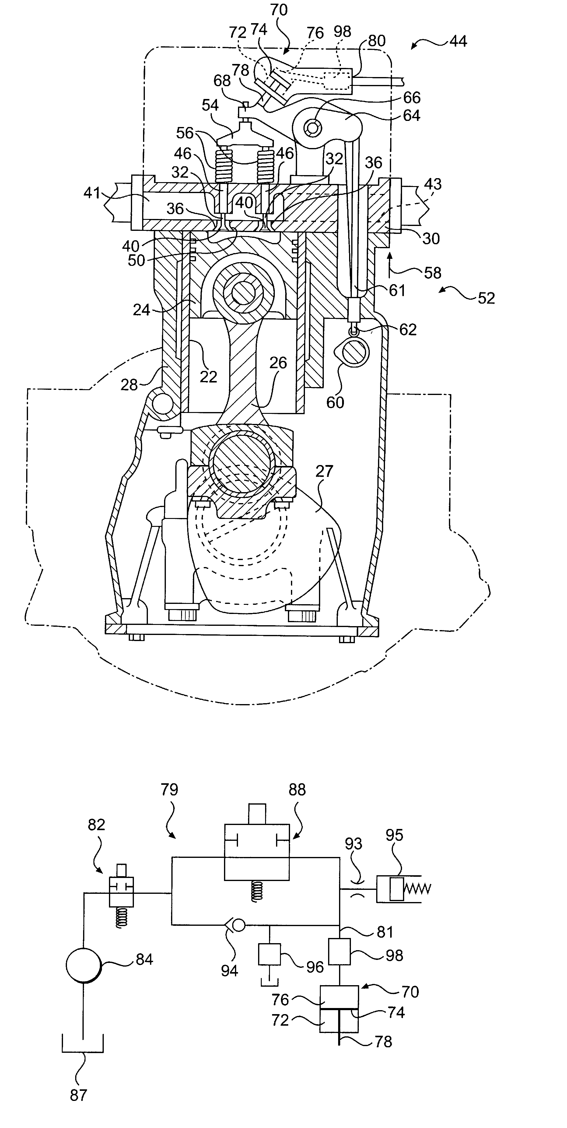
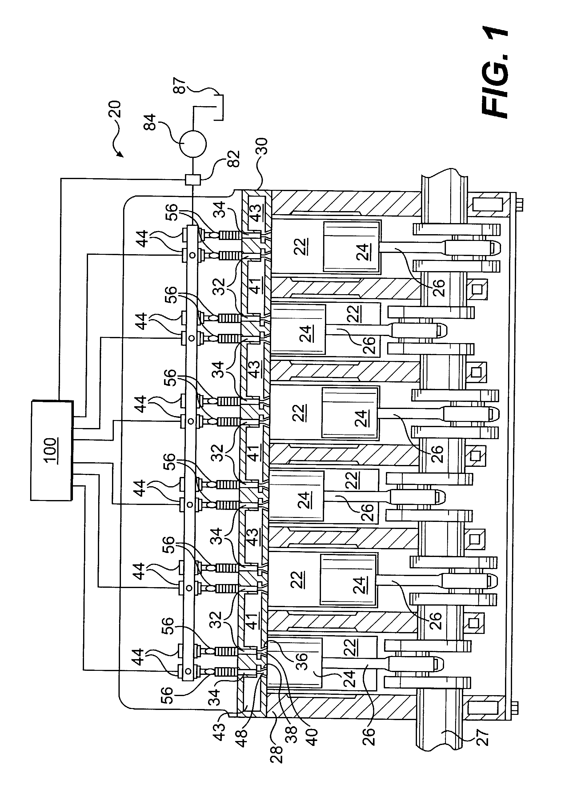
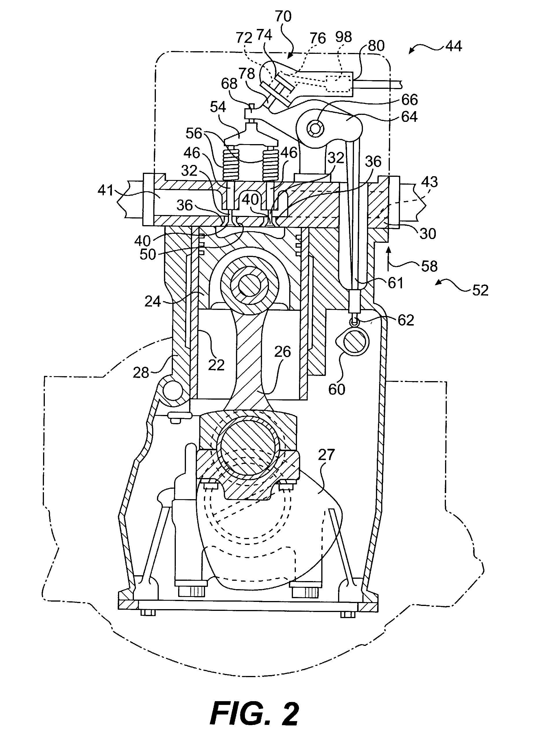
[0022]An exemplary embodiment of an internal combustion engine 20 is illustrated in FIG. 1. For the purposes of the present disclosure, engine 20 is depicted and described as a four stroke diesel engine. One skilled in the art will recognize, however, that engine 20 may be any other type of internal combustion engine, such as, for example, a gasoline or natural gas engine.

[0023]As illustrated in FIG. 1, engine 20 includes an engine block 28 that defines a plurality of cylinders 22. A piston 24 is slidably disposed within each cylinder 22. In the illustrated embodiment, engine 20 includes six cylinders 22 and six associated pistons 24. One skilled in the art will readily recognize that engine 20 may include a greater or lesser number of pistons 24 and that pistons 24 may be disposed in an “in-line” configuration, a “V” configuration, or any other conventional configuration.

[0024]As also shown in FIG. 1, engine 20 includes a crankshaft 27 that is rotatably disposed within engine block...


PUM


Abstract

An engine valve actuation system is provided. The engine valve actuation system includes an intake valve that is moveable between a first position to prevent a flow of fluid and a second position to allow a flow of fluid. A cam assembly is configured to move the intake valve between the first position and the second position. A fluid actuator is configured to selectively prevent the intake valve from moving to the first position. A source of fluid is in fluid communication with the fluid actuator. A directional control valve is configured to control a flow of fluid between the source of fluid and the fluid actuator. A fluid passageway connects the directional control valve with the fluid actuator. An accumulator is in fluid communication with the fluid passageway. A restricted orifice is disposed between the accumulator and the fluid passageway to restrict a flow of fluid between the accumulator and the fluid passageway.

Description

RELATED APPLICATIONS[0001]This is a continuation-in-part of application Ser. No. 10 / 144,062, filed May 14, 2002 which is incorporated herein by reference.TECHNICAL FIELD[0002]The present invention is directed to an engine valve actuation system. More particularly, the present invention is directed to a valve actuation system for an internal combustion engine.BACKGROUND[0003]The operation of an internal combustion engine, such as, for example, a diesel, gasoline, or natural gas engine, may cause the generation of undesirable emissions. These emissions, which may include particulates and nitrous oxide (NOx), are generated when fuel is combusted in a combustion chamber of the engine. An exhaust stroke of an engine piston forces exhaust gas, which may include these emissions from the engine. If no emission reduction measures are in place, these undesirable emissions will eventually be exhausted to the environment.[0004]Research is currently being directed towards decreasing the amount o...

Claims


Application Information

Patent Timeline
Patent Type & Authority Patents(United States)
IPC IPC(8): F01L9/02F01L1/18F01L1/14F01L1/26F01L9/10F01L9/12F01L13/00F01L13/06F02D13/02F02D15/00F02D15/04F02D41/04F02D45/00
CPCF01L1/146F01L9/02F01L9/023F01L13/0015F01L13/06F01L13/065F02D13/0269F01L1/26Y02T10/142F01L2001/34446F01L2013/0089F01L2105/00F01L2800/00F02B2275/32F02D15/04F01L2305/00Y02T10/12F01L9/12F01L9/10
Inventor CORNELL, SEAN O.LEMAN, SCOTT ALAN
Owner CATERPILLAR INC
Why Eureka
Try Eureka