Cooled turbine vane platform

a technology of cooling turbines and vane platforms, which is applied in the direction of propellers, air transport, water-acting propulsive elements, etc., can solve the problems of u.s. pat. no. 5,417,545 being susceptible to the limited cooling ability of thin air films

Active Publication Date: 2006-02-28
PRATT & WHITNEY CANADA CORP
View PDF12 Cites 46 Cited by
  • Summary
  • Abstract
  • Description
  • Claims
  • Application Information

AI Technical Summary

Benefits of technology

[0003]It is accordingly an object of the present invention to provide improved cooling to a turbine vane in a gas turbine engine.
[0006]There is further provided, in accordance with the present invention, a method of cooling a vane assembly disposed in a gas path of a gas turbine engine, the vane assembly having a plurality of airfoils radially extending between inner and outer platforms, the method comprising: determining regions on the inner and outer platforms which experience highest gas flow temperatures; providing a plurality of holes in at least one of the inner and outer platforms and in at least the regions thereof substantially intermediate adjacent airfoils; directing compressed cooling air to inlets of the holes; and effusing the cooling air through the holes out into the gas path intermediate adjacent airfoils to cool the vane assembly.

Problems solved by technology

However, the solution of U.S. Pat. No. 5,417,545 is susceptible to the limited cooling ability of the thin air film in the face of the extreme temperatures, turbulence and varied temperature distribution of the combustion gases.

Method used


Image

  • Cooled turbine vane platform
  • Cooled turbine vane platform
  • Cooled turbine vane platform

Examples


Embodiment Construction

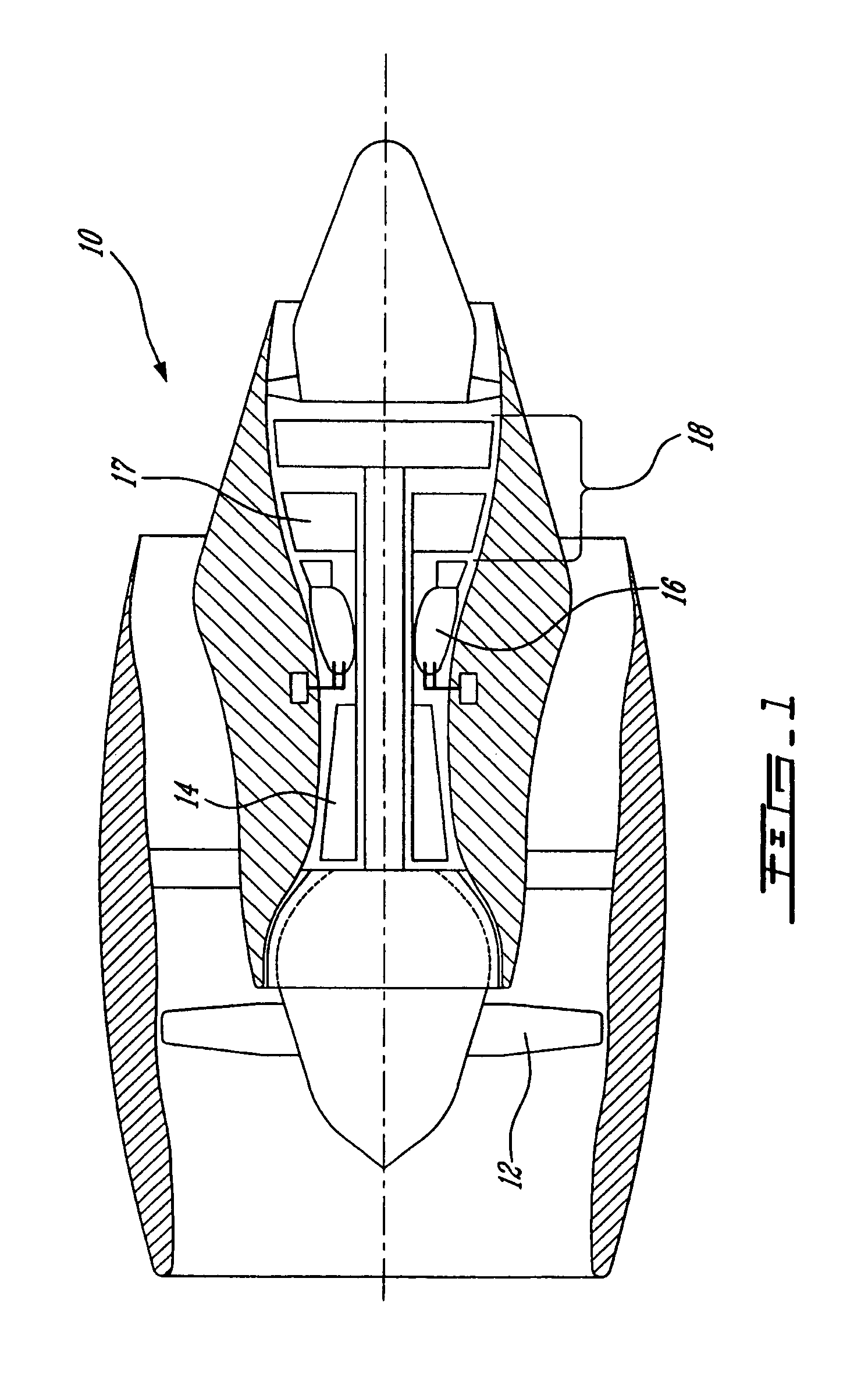
[0017]FIG. 1 schematically illustrates a gas turbine engine 10 (a turbofan preferably adapted for use on an aircraft in subsonic flight in this case, though the invention may be practised in almost any gas turbine engine) generally comprising, in serial flow communication, a fan 12 through which ambient air is propelled, a multistage compressor 14 for pressurizing the air, a combustor 16 in which the compressed air is mixed with fuel and ignited for generating an annular stream of hot combustion gases, and a turbine section 18 for extracting energy from the combustion gases.

[0018]The turbine section 18 may comprise one or more turbine stages, in this case two are shown including a first, or high pressure (HP), turbine stage 17, which includes a turbine rotor with a plurality of radially extending turbine blades and a turbine vane assembly in accordance with the present invention.

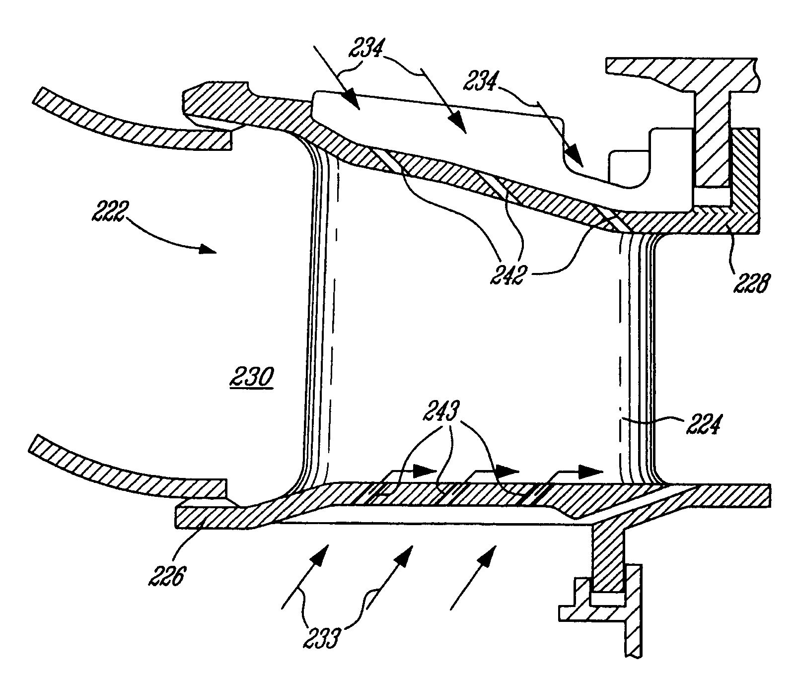
[0019]Referring now to FIGS. 4 to 6, the turbine vane assembly 22 of the present invention provides impro...


PUM


Abstract

A vane assembly for a gas turbine engine comprises a plurality of airfoils extending between platforms and a plurality of effusion holes which are defined in at least one of the inner and outer platforms in a region intermediate adjacent airfoils. The effusion holes provide fluid flow communication between a cooling air source and the gas path.

Description

TECHNICAL FIELD[0001]The present invention relates generally to gas turbine engines, and more particularly to cooling turbine vanes therein.BACKGROUND OF THE INVENTION[0002]Turbine vane cooling improves component life. Vane platforms may be externally impingement cooled, as shown in FIG. 2, in which a cooling air flow 919 is directed to the plenum 916, thereby convectively cooling the outer surface 918 of the vane platform 915. It is also known to cool turbine vane platforms by film cooling, as shown in FIGS. 3a and 3b, and described in U.S. Pat. No. 5,417,545. A plurality of regularly-spaced cooling holes 922 in the platform 915, upstream of the airfoils 912, permit a cooling airflow to enter the gas path 917 and form a uniform film or blanket 924 of cool air on the vane platform in an attempt to insulate it from the hot gases. However, the solution of U.S. Pat. No. 5,417,545 is susceptible to the limited cooling ability of the thin air film in the face of the extreme temperatures,...

Claims


Application Information

Patent Timeline
Patent Type & Authority Patents(United States)
IPC IPC(8): F01D5/18F01D9/04F01D25/14
CPCF01D9/041F01D25/14F05D2260/203F05D2240/81Y02T50/676Y02T50/60
Inventor SYNNOTT, REMYTRINDADE, RICARDO
Owner PRATT & WHITNEY CANADA CORP
Why Eureka
Try Eureka