Method of fabrication of a dryer fabric and a dryer fabric with backside venting for improved sheet stability

a dryer fabric and fabric technology, applied in the field of papermaking arts, can solve the problems of reducing machine efficiency, reducing paper product quality, and leaving a fibrous web on the surfa

Inactive Publication Date: 2006-02-28
ALBANY INT CORP
View PDF94 Cites 72 Cited by
  • Summary
  • Abstract
  • Description
  • Claims
  • Application Information

AI Technical Summary

Benefits of technology

[0017]Accordingly, the present invention relates primarily to a dryer fabric, although it may find application in any of the fabrics used in the forming, pressing and drying sections of a paper machine, and in the industrial fabrics used in the manufacture of nonwoven fabrics. As such, the papermaker's or industrial fabric comprises a base substrate which takes the form of an endless loop having a backside and a paper-contacting side. A plurality of discrete, discontinuous deposits of polymeric resin material are disposed at preselected locations on the backside. These deposits have a height, relative to the backside, of at least 0.5 mm so that they may separate the backside from the surface of a dryer cylinder or turning roll by that amount when passing therearound. The deposits allow air trapped between the backside and the surface of the dryer cylinder to escape in both the lengthwise and crosswise directions parallel to the surface rather than through the fabric to alleviate the problem of “drop off”.

Problems solved by technology

A large amount of water is drained from the slurry through the forming fabric during this process, leaving a fibrous web on its surface.
“Drop off” can reduce the quality of the paper product being manufactured by causing edge cracks.
“Drop off” can also reduce machine efficiency if it leads to sheet breaks.
Both of these expedients allow the air otherwise trapped in the compression wedge to be removed without passing through the dryer fabric, although both are expensive.
However, this significant reduction in permeability is unacceptable for dryer fabric applications.

Method used


Image

  • Method of fabrication of a dryer fabric and a dryer fabric with backside venting for improved sheet stability
  • Method of fabrication of a dryer fabric and a dryer fabric with backside venting for improved sheet stability
  • Method of fabrication of a dryer fabric and a dryer fabric with backside venting for improved sheet stability

Examples


Embodiment Construction

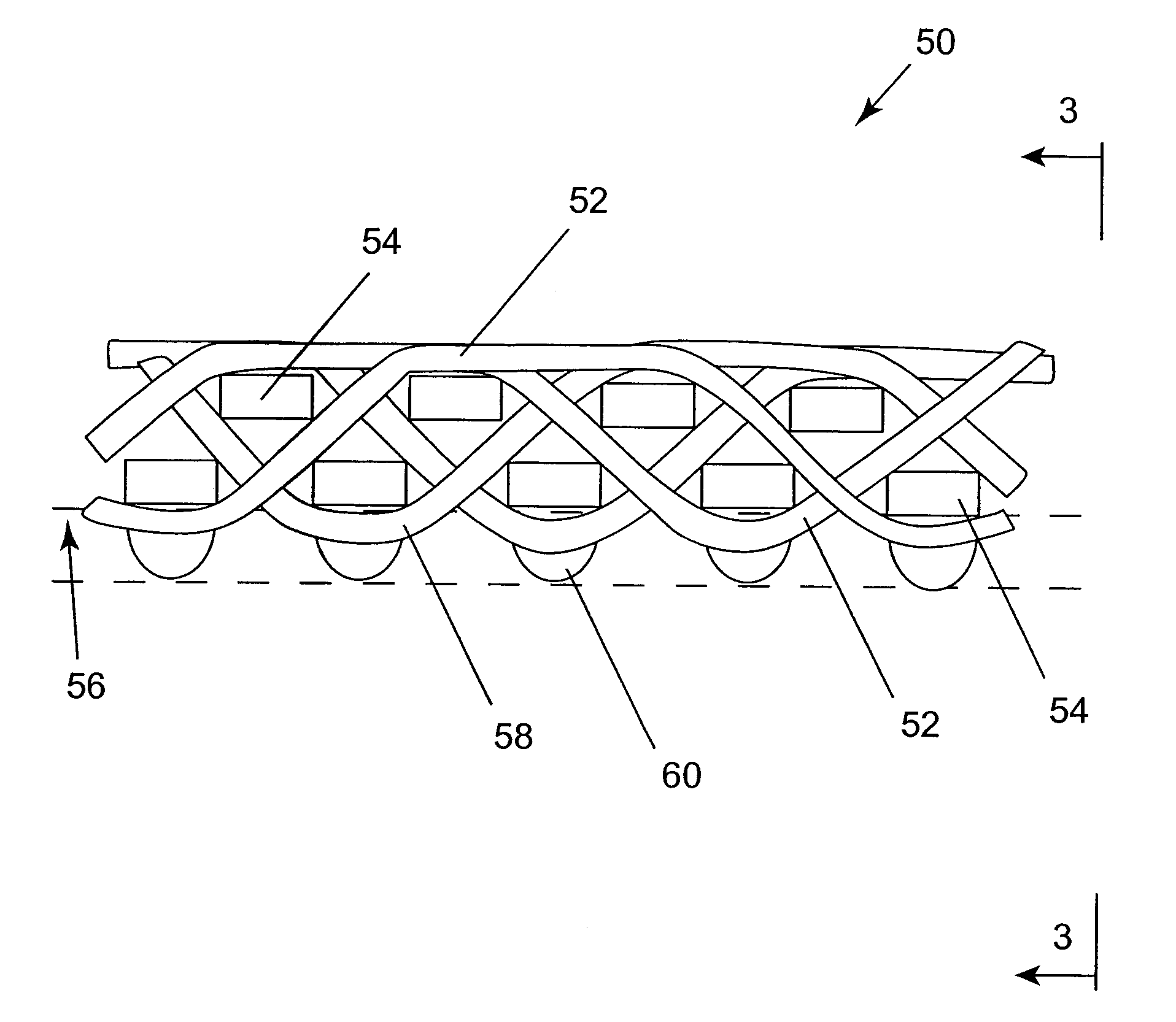
[0031]The method for fabricating the papermaker's or industrial fabric of the present invention begins with the provision of a base substrate. Typically, the base substrate is a fabric woven from monofilament yarns. More broadly, however, the base substrate may be a woven, nonwoven or knitted fabric comprising yarns of any of the varieties used in the production of paper machine clothing or industrial fabrics used to manufacture nonwoven articles and fabrics, such as monofilament, plied monofilament, multifilament and plied multifilament yarns. These yarns may be obtained by extrusion from any of the polymeric resin materials used for this purpose by those of ordinary skill in the art. Accordingly, resins from the families of polyamide, polyester, polyurethane, polyaramid, polyolefin and other resins may be used.

[0032]Alternatively, the base substrate may be composed of mesh fabrics, such as those shown in commonly assigned U.S. Pat. No. 4,427,734 to Johnson, the teachings of which ...


PUM

PropertyMeasurementUnit
heightaaaaaaaaaa
heightaaaaaaaaaa
heightsaaaaaaaaaa

Abstract

A method of manufacturing and a papermaker's or industrial fabric, such as a dryer fabric for the dryer section of a paper machine, includes the application of a polymeric resin material onto preselected locations on the backside of a base substrate using a piezojet array which deposits the polymeric resin material in droplets having an average diameter of 10μ (10 microns) or more to build up discrete, discontinuous deposits of the polymeric resin material having a height of about 0.5 mm at the preselected locations. The preselected locations may be the knuckles formed by the interweaving of the yarns making up the fabric. The purpose of the deposits is to separate the backside of the dryer fabric from a surface, such as that of a dryer cylinder or turning roll, to enable air trapped between the dryer fabric and the surface to escape in lengthwise and crosswise directions parallel to the surface, instead of being forced through the fabric, possibly causing “drop off”. The polymeric resin material is set by means appropriate to its composition, and, optionally, and, if necessary, may be abraded to provide the deposits with a uniform height above the surface plane of the base substrate.

Description

BACKGROUND OF THE INVENTION[0001]1. Field of the Invention[0002]The present invention relates to the papermaking arts. More specifically, the present invention relates to the papermaker's fabrics used on the dryer section of a paper machine, and particularly on a single-run dryer section. Such fabrics are commonly referred to as dryer fabrics.[0003]2. Description of the Prior Art[0004]As is well known to those of ordinary skill in the art, the papermaking process begins with the deposition of a fibrous slurry, that is, an aqueous dispersion of cellulosic fibers, onto a moving forming fabric in the forming section of a paper machine. A large amount of water is drained from the slurry through the forming fabric during this process, leaving a fibrous web on its surface.[0005]The newly formed web proceeds from the forming section to a press section, which includes a series of press nips. The fibrous web passes through the press nips supported by a press fabric, or, as is often the case,...

Claims


Application Information

Patent Timeline
Patent Type & Authority Patents(United States)
IPC IPC(8): D21F1/10B05D1/40B32B27/12D21F7/12D04H1/46D21F1/00
CPCD04H1/465D21F1/0027D21F1/0036Y10T428/269Y10S162/902Y10T428/2481Y10T442/3195Y10T442/2098Y10T442/3179Y10T442/273Y10T442/2139D03D13/00B05D1/02D21F5/00D03D25/00D04H1/46
Inventor TONEY, MARY M.PAQUIN, MAURICE
Owner ALBANY INT CORP
Why Eureka
Try Eureka