Electrophoresis in microfabricated devices using photopolymerized polyacrylamide gels and electrode-defined sample injection

a technology of photopolymerization and polyacrylamide gels, applied in the direction of liquid/fluent solid measurement, fluid pressure measurement, peptides, etc., can solve the problems of unoptimized gel resolution, large size of sample injection, and inability to meet the requirements of modern laboratories, so as to achieve the effect of reducing cost, reducing time, and superior resolution

Inactive Publication Date: 2006-02-28
RGT UNIV OF MICHIGAN
View PDF5 Cites 31 Cited by
  • Summary
  • Abstract
  • Description
  • Claims
  • Application Information

AI Technical Summary

Benefits of technology

[0009]In one embodiment, the present invention relates to a novel, small-scale, electrophoretic separation system based on photodefined polymers (e.g., polyacrylamide gels) and electrode-defined sample injection giving superior resolution at a reduced cost and in less time.
[0010]In one embodiment, the present invention contemplates an ultra-short, integrated sample compaction and separation system using the techniques of the silicon microfabrication industry. Although the present invention is not limited to any particular mechanism, it is believed the use of photopolymerized polymer (e.g., polyacrylamide) sieving matrices overcomes many of the drawbacks of conventional polyacrylamide gel preparation. The present invention can reproducibly resolve a dsDNA standard of about 20 bp well into about the 500 bp range in just a few millimeters. The individual bands are clearly observed and appear essentially identical to a macro-scale electrophoresis separation. Since varying the polymer polymerization time strongly influences the structure and sieving properties of the polymerized polymer, a further potential advantage of the UV initiated chemistry of the present invention is the ability to tailor the pore structure of a single polymer by appropriate modulation of polymerization conditions.
[0011]In one embodiment, the present invention contemplates the use of microelectrodes. Although not limited to any particular mechanism, it is believed that the use of microelectrodes offers the ability to precisely define the shape and size of the injected sample plug by simple manipulation of the design of compaction electrode. Unlike standard electrokinetic injection schemes, almost an order of magnitude increase in the sample concentration can be achieved using the technique of the present invention with no additional broadening of the sample plug. The use of microelectrodes is not limited to low voltages and short injection distances. High voltages, especially with DC current, are also contemplated. Additionally, it is contemplated that adverse electrolytic effects, if any, can be minimized by using a permeation layer of agarose or acrylamide as is currently done in active DNA hybridization microchips (Heller, M., et al., Electrophoresis 21:157–164, 2000). Alternatively, microfabrication offers the possibility of depositing a bank of compaction electrodes with no change in process cost or complexity. Creative placement and activation of electrodes will result in far greater concentration enhancement.

Problems solved by technology

Genotyping projects on the order of millions of assays, however, are beyond the capabilities of today's laboratories because of the current inefficiencies in (i) liquid handling of reagent and DNA template solutions, (ii) measurement of solution volumes, (iii) mixing of reagent and template, (iv) controlled thermal reaction of the mixed solutions, (v) sample loading onto an electrophoresis gel and (vi) DNA product detection on size-separating gels.
However, these prior art techniques leave much to be desired in that gel resolution is non-optimal and the procedures and equipment are not economical to procure and use.

Method used


Image

  • Electrophoresis in microfabricated devices using photopolymerized polyacrylamide gels and electrode-defined sample injection
  • Electrophoresis in microfabricated devices using photopolymerized polyacrylamide gels and electrode-defined sample injection
  • Electrophoresis in microfabricated devices using photopolymerized polyacrylamide gels and electrode-defined sample injection

Examples


example 2

Photopolymerized Polyacrylamide Gels

[0093]Having selected the commercially available UV initiated ReproGel™ formulation, the gel casting process was greatly simplified. Two variations of the polymerization mixture were studied: ReproGel™ High Resolution, containing 8% (w / v) acrylamide / bisacrylamide monomers and 1× TBE buffer, and ReproGel™ Long Read, containing 7% (w / v) acrylamide / bisacrylamide monomers and 1.5× TBE buffer. The characteristically small dimensions of microfabricated separation channels demand that care be taken to preserve the integrity of the gel during the casting process by avoiding the introduction of impurities and eliminating bubble formation during the polymerization reaction. However, we found that reproducible high-resolution separations were achievable using the as-received reagents, without the need for additional purification and / or degassing.

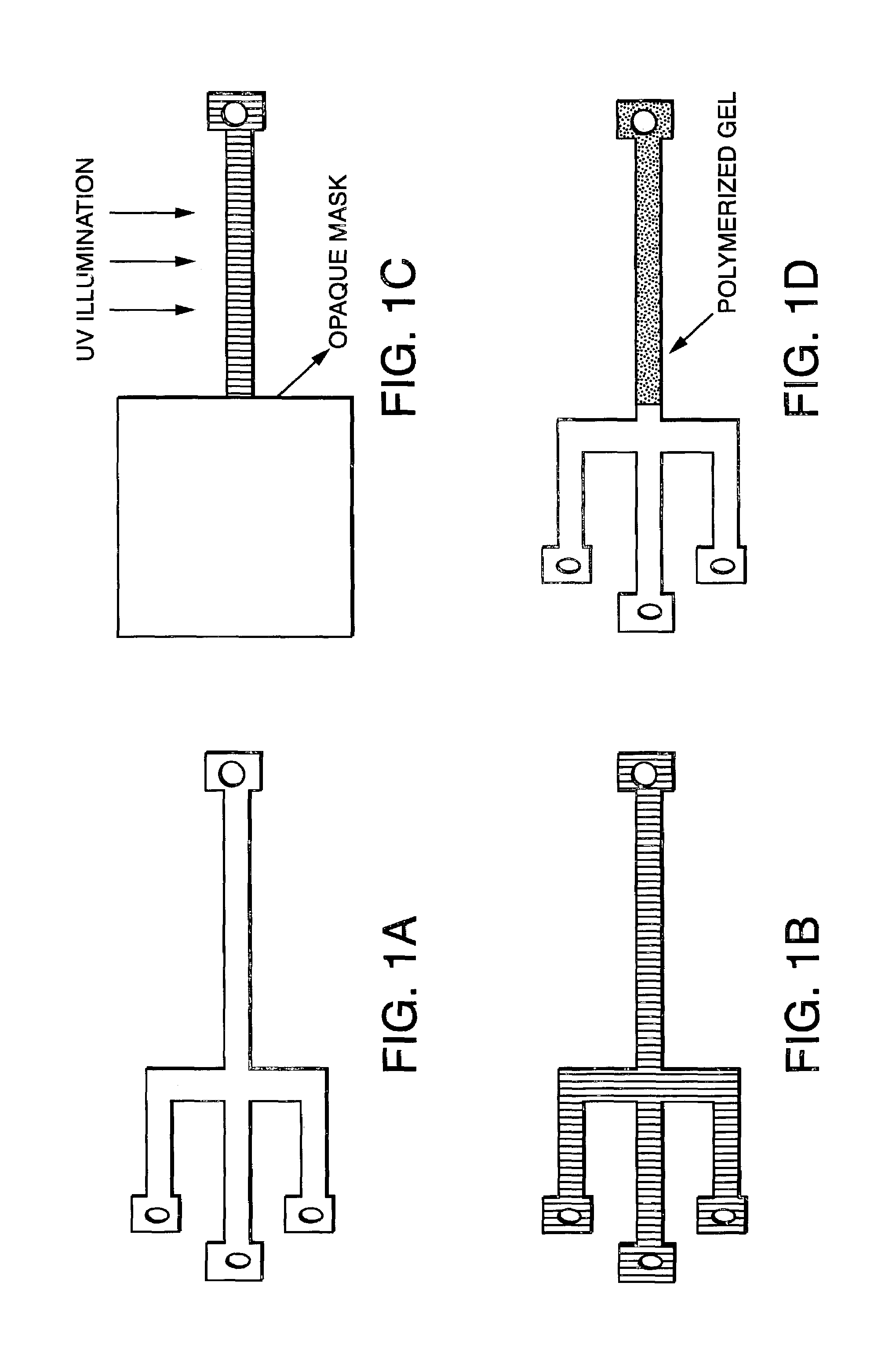
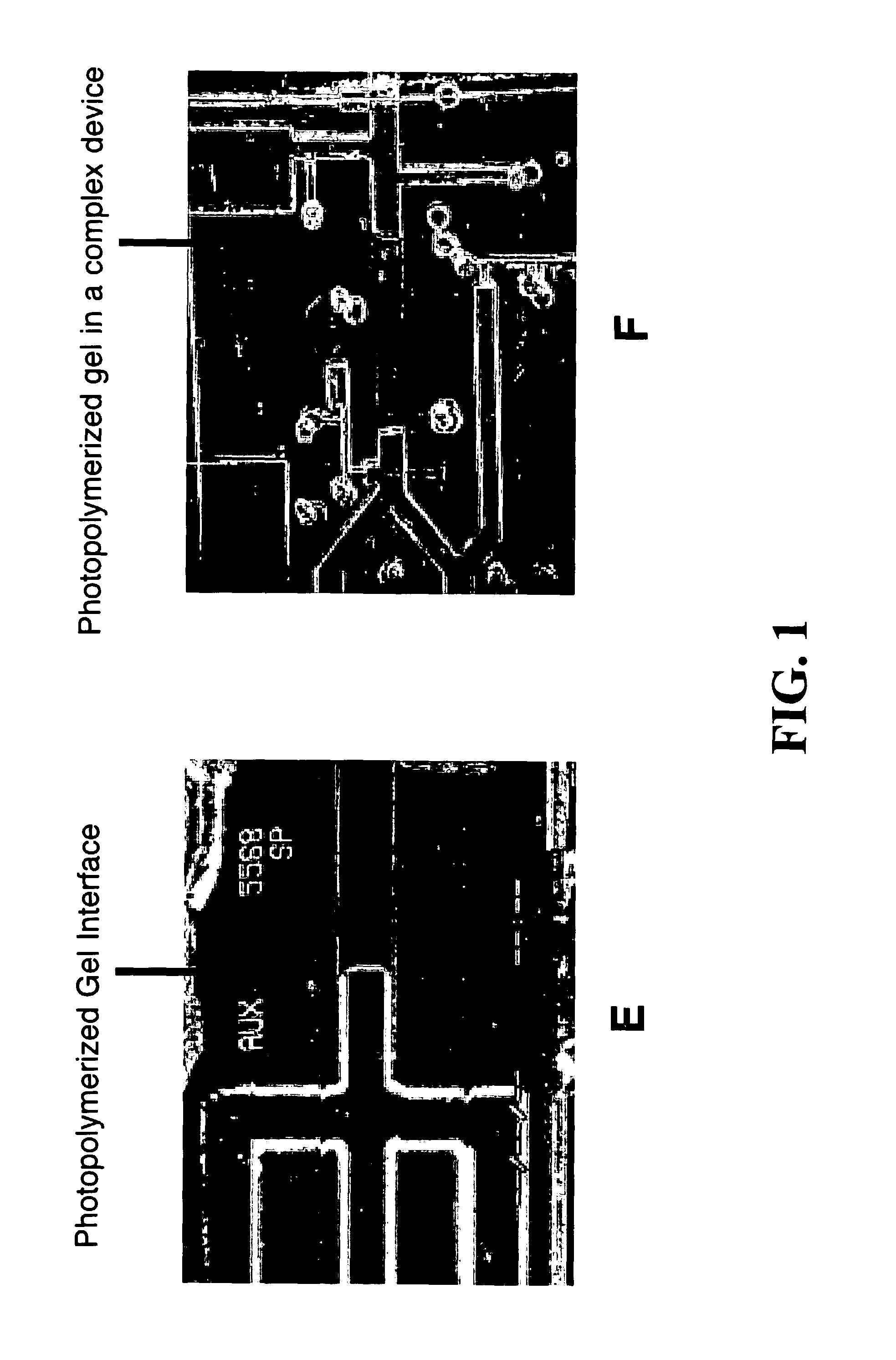
[0094]Flat and uniform gel interfaces in the sample loading region could be achieved by partially filling the chan...

example 3

Optimization Of Photopolymerization Time

[0096]Optimization of the polymerization protocol focused on adjusting UV intensity and polymerization time, both of which strongly affect the rate of initiation, with the aim of maximizing separation performance with minimal run-to-run variability. The Reproset™ UV illumination source (Amersham Pharmacia, Kalamazoo, Mich.), designed specifically for use with the ReproGel™ reagents, provided more consistent results than a lower-intensity UV lamp (UVP, San Gabriel, Calif.) and was used as provided in the manufacturers materials. Separation performance was evaluated by observing the migration of a fluorescently labeled 20 base pair molecular ladder (FIGS. 2a–d; samples were directly compacted at the gel interface by application of an electric field (E=10 V / cm) for 20 s. Separation was conducted at E=20 V / cm. Migration direction is left to right. Data shown corresponds to gel polymerization times of (a) 2, (b) 6, (c) 7 and (d) 8 minutes. The doub...

example 4

Microseparations Using Photopolymerized Polyacrylamide

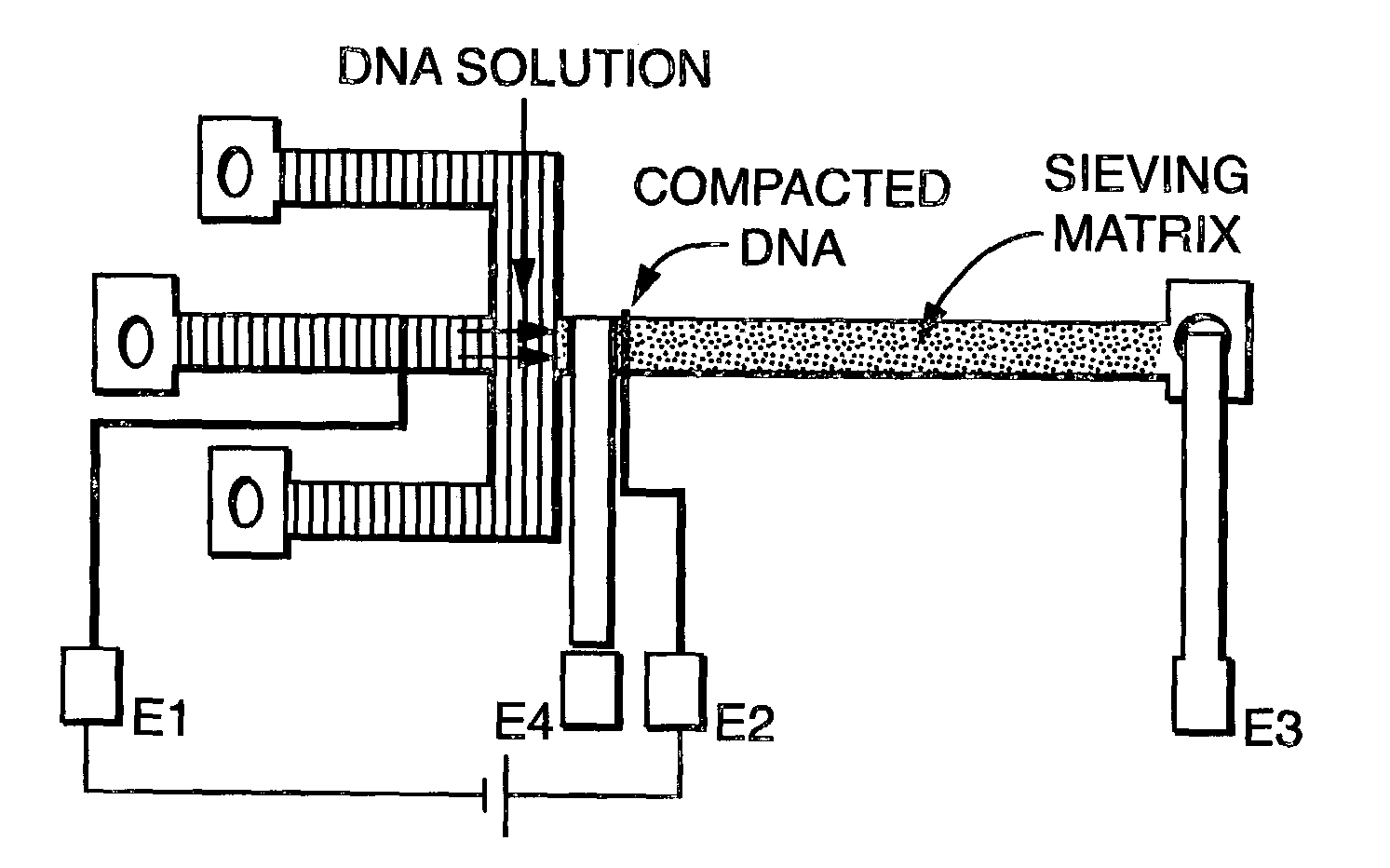
[0099]The first step in electrophoresis after loading the sieving matrix is sample injection. Sample injection in a non-crosslinked sieving media is normally executed electrokinetically using a cross channel with the sample channel perpendicular to the separation channel. For crosslinked media, electrophoretic injection was used. In this technique, a short pulse of a relatively high electric field (10 V / cm for 10 to 20 seconds) was applied between the ends of the separation channel, resulting in compaction of the sample at the gel interface as a consequence of the discontinuity in electrophoretic mobilities inside and outside the gel. After compaction, the field was switched off and the injection ports are flushed with buffer solution. Alternatively, electric fields can be used to achieve an electronic flush to prevent excess sample from entering the separation matrix. Finally, the field was switched back on and increased to the ...


PUM

PropertyMeasurementUnit
separation lengthaaaaaaaaaa
volumeaaaaaaaaaa

Abstract

The present invention relates to a novel, small-scale, electrophoretic separation system based on photodefined polymers and electrode-defined sample injection. Diffusion and displacement coefficients may be modified by varying the gel concentration, the intensity of the incident UV radiation and the temperature at which the gel is run. The device is an major advance over current technology since it provides for a significant reduction in size of the micro-electrophoresis apparatus and a significant cost savings.

Description

[0001]This application for patent under 35 U.S.C. 111(a) claims priority to U.S. Provisional Application Ser. No. 60 / 346,214 filed on Oct. 24, 2001 under 35 U.S.C. 111(b).[0002]This invention was made with funding from the National Institutes of Health; Grant Number 1 PO1 HG01984-01. The government may have certain rights in this invention.FIELD OF THE INVENTION[0003]The present invention relates to a novel, small-scale, electrophoretic separation system based on photodefined polymers (e.g., polyacrylamide gels) and electrode-defined sample injection giving superior resolution at a reduced cost and in less time.BACKGROUND OF INVENTION[0004]Despite the progress made towards the development of microfabricated DNA analysis systems, there are significant hurdles to the realization of small, portable DNA analysis systems. Although the cross sectional dimensions of typical microfabricated electrophoresis channels are on the order of those employed in conventional capillary systems, scale-...

Claims


Application Information

Patent Timeline
Patent Type & Authority Patents(United States)
IPC IPC(8): G01N27/447
CPCG01N27/44704G01N27/44791G01N27/44743
Inventor BURNS, MARK A.BRAHMASANDRA, SUNDARESH N.UGAZ, VICTOR M.
Owner RGT UNIV OF MICHIGAN
Why Eureka
Try Eureka