Transparent substrate with an antireflection, low-emissivity or solar-protection coating

a technology of transparent substrates and solar protection coatings, applied in the field of transparent substrates, can solve problems such as unsatisfactory stability

Inactive Publication Date: 2006-02-28
SEKURIT SAINT GOBAIN DEUT
View PDF28 Cites 71 Cited by
  • Summary
  • Abstract
  • Description
  • Claims
  • Application Information

AI Technical Summary

Benefits of technology

[0015]In a third embodiment, the thin layer of titanium oxide is modified by lowering the density of the titanium oxide thin layer to a value that is 80 to 95 percent of the theoretical density of titanium oxide.

Problems solved by technology

For example, although incorporating it into an antireflection coating allows very low levels of reflection to be achieved, it is not optimal with regard to the “stability” of the appearance of the coated substrate in reflection.

Method used


Image

  • Transparent substrate with an antireflection, low-emissivity or solar-protection coating
  • Transparent substrate with an antireflection, low-emissivity or solar-protection coating
  • Transparent substrate with an antireflection, low-emissivity or solar-protection coating

Examples


example 1

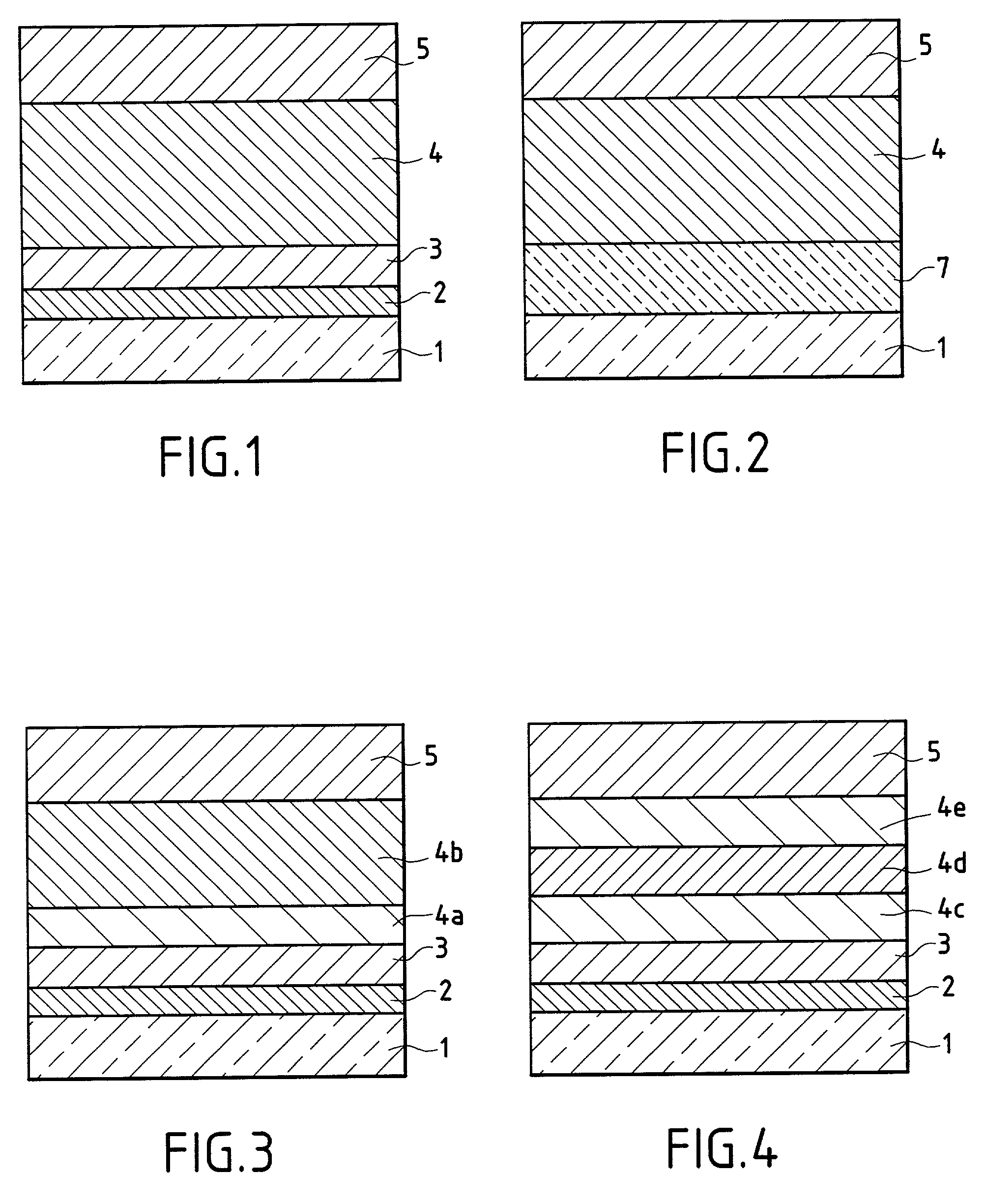
[0073]This example corresponds to FIG. 1 and comprises a glass 1 coated with an antireflection multilayer stack according to the invention 6 which is composed of two high-index thin layers 2, 4 and two low-index thin layers 3, 5. The low-index layer 3 is made of SiO2; the low-index layer 5 is a mixture of silicon and aluminum oxides SiAlxOy (approximately 10 atomic percent % of Al with respect to Si); the high-index layer 2 is made of SnO2; and the high-index layer 4 is titanium oxide modified by partial nitridation according to the invention, the material corresponding to the formula TiOxNy with the level of nitridation being adjusted in order to achieve a refractive index of about 2.35 at 580 nm, i.e., a nitrogen ratio in percent by volume, N2 / (N2+O2+Ar), of about 15 to 20% in the deposition chamber.

[0074]Table 1 below gives the index and the physical and optical thicknesses of the layers in the multilayer stack.

[0075]

TABLE 1PhysicalOpticalGlass (1)IndexThickness (nm)Thickness (nm...

example 2

[0076]This example repeats the multilayer stack of Example 1, but replaces, as shown in FIG. 2, the layers 2 and 3 with a single intermediate-index layer 7 made of silicon oxynitride SiOxNy, the nitrogen content of which is varied in order to adjust the index to a value of about 1.78.

[0077]Table 2 gives the index and the physical and optical thicknesses of the layers in the multilayer stack for this three-layer coating.

[0078]

TABLE 2PhysicalOpticalGlass (1)IndexThickness (nm)Thickness (nm)SiOxNy (7) 1.7860107TIOxNy (4)≈2.35  118.5 278SiAlxOy (5)≈1.4885126

example 3

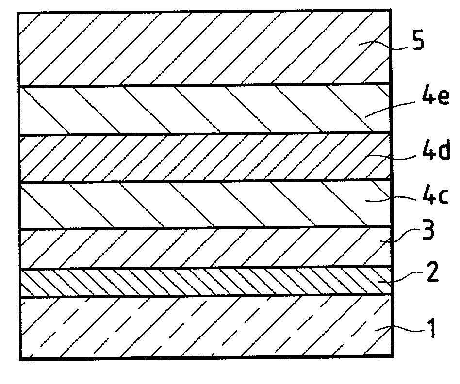
[0079]This example repeats the three-layer stack configuration of Example 2, but uses another type of modified titanium oxide layer. Instead of layer 4 being TiOxNy, layer 4 is a layer of titanium oxide containing tantalum with a Ta / Ti atomic percent proportion in the layer of about 10 to 15%, preferably 13% (a Ti—Ta alloy target in suitable proportions is used), so that the index of the layer is about 2.33 to 2.40, preferably 2.35 (the optical thicknesses are the same as in Example 2).

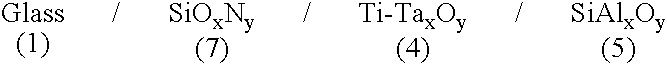
[0080]The following multilayer stack is therefore obtained:

[0081]It was confirmed that the tantalum-modified titanium oxide allowed deposition rates to be achieved that were 40% higher than those with TiO2.


PUM

PropertyMeasurementUnit
refractive indexaaaaaaaaaa

Abstract

A transparent substrate and methods of making a transparent substrate having, on at least one of its faces, an antireflection coating made of a multilayer stack of alternating thin layers of high and low refractive indices. Preferably, the thin layers are based on a dielectric material. At least one of the thin high-index layers comprises titanium oxide which is modified so as to reduce its refractive index to a value of at most 2.40, preferably to a value of at most 2.35.

Description

CROSS REFERENCE TO RELATED APPLICATIONS[0001]This application is a continuation of the U.S. national stage designation of International Application No. PCT / FR00 / 01313, filed May 17, 2000, the contents of which are expressly incorporated herein by reference thereto.BACKGROUND OF THE INVENTION[0002]The invention relates to transparent substrates based on organic polymer(s) or glass, that are provided with an antireflection coating and to their method of manufacture. The invention further relates to their use, especially as glazing.BACKGROUND OF THE INVENTION[0003]An antireflection coating typically consists of a multilayer stack comprising interferential thin layers, generally of alternating layers having high and low refractive indices. When deposited on a transparent substrate, the antireflection coating has the function of reducing its light reflection, and therefore increasing its light transmission. Therefore, a coated substrate has its ratio of transmitted light / reflected light ...

Claims


Application Information

Patent Timeline
Patent Type & Authority Patents(United States)
IPC IPC(8): B32B17/06B32B7/02B32B9/00B32B17/10C03C17/34G02B1/11
CPCB32B17/10036B32B17/10174B32B17/10761G02B1/116C03C17/3435G02B1/115C03C17/3417C03C2217/734C03C17/366G02B1/18G02B1/16C03C27/10G02B1/11
Inventor ANDERSON, CHARLESNADAUD, NICOLAS
Owner SEKURIT SAINT GOBAIN DEUT
Why Eureka
Try Eureka