Crystal oscillator with temperature compensated through a vibrator current control circuit

a technology of vibrator current control circuit and crystal oscillator, which is applied in the direction of oscillator stabilization, oscillator generator, electrical apparatus, etc., can solve the problem that functions necessarily interfere with the variable range, and achieve the effect of reducing frequency distortion

Inactive Publication Date: 2006-02-28
SEIKO EPSON CORP
View PDF3 Cites 2 Cited by
  • Summary
  • Abstract
  • Description
  • Claims
  • Application Information

AI Technical Summary

Benefits of technology

[0030]In the light of the above problems, it is an object of the present invention to provide a temperature compensated crystal oscillator that can obtain a large variable range and that can obtain high temperature stability that the conventional oscillator having two or more load capacitance variable functions cannot achieve by controlling a vibrator current.
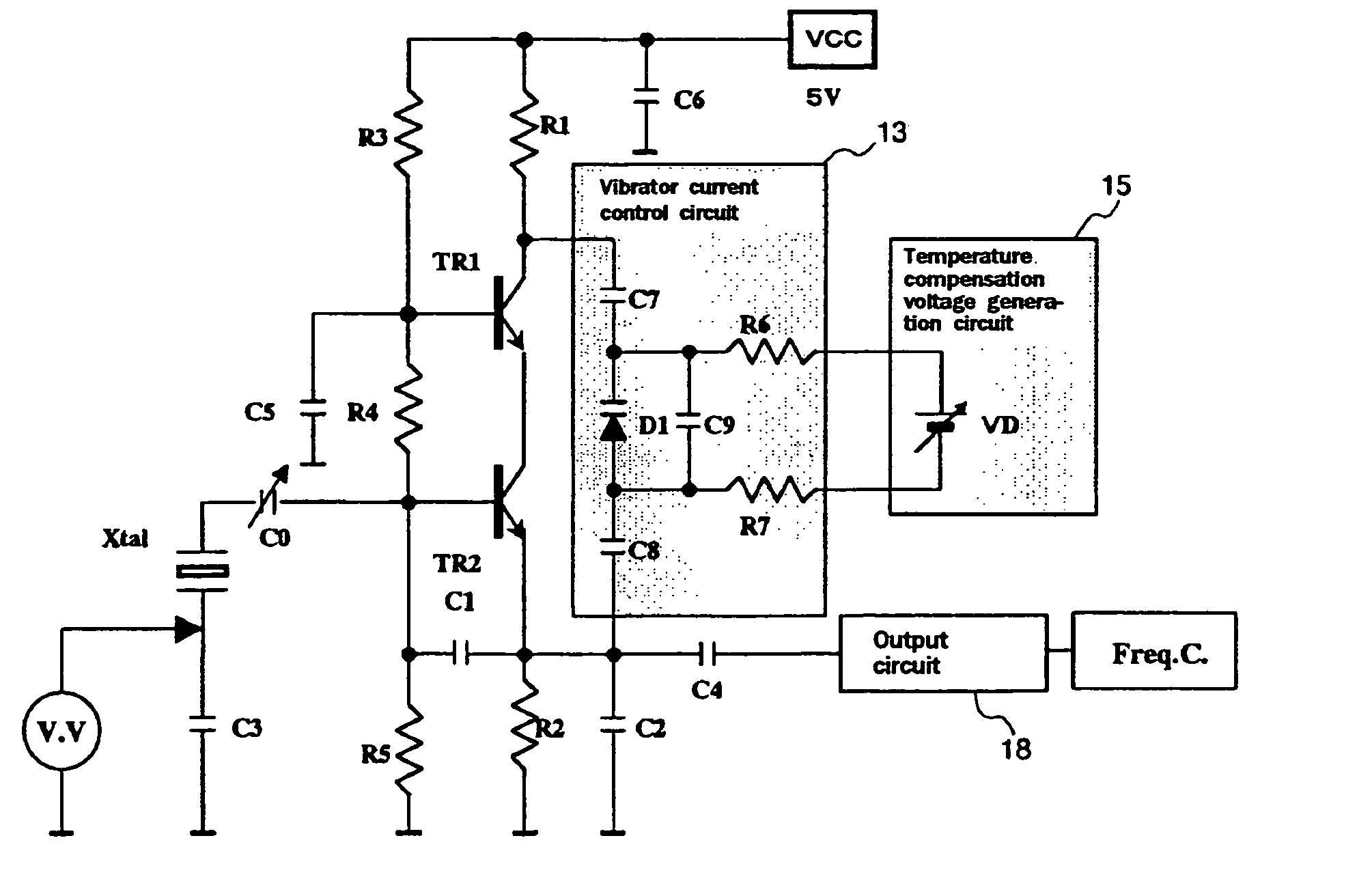
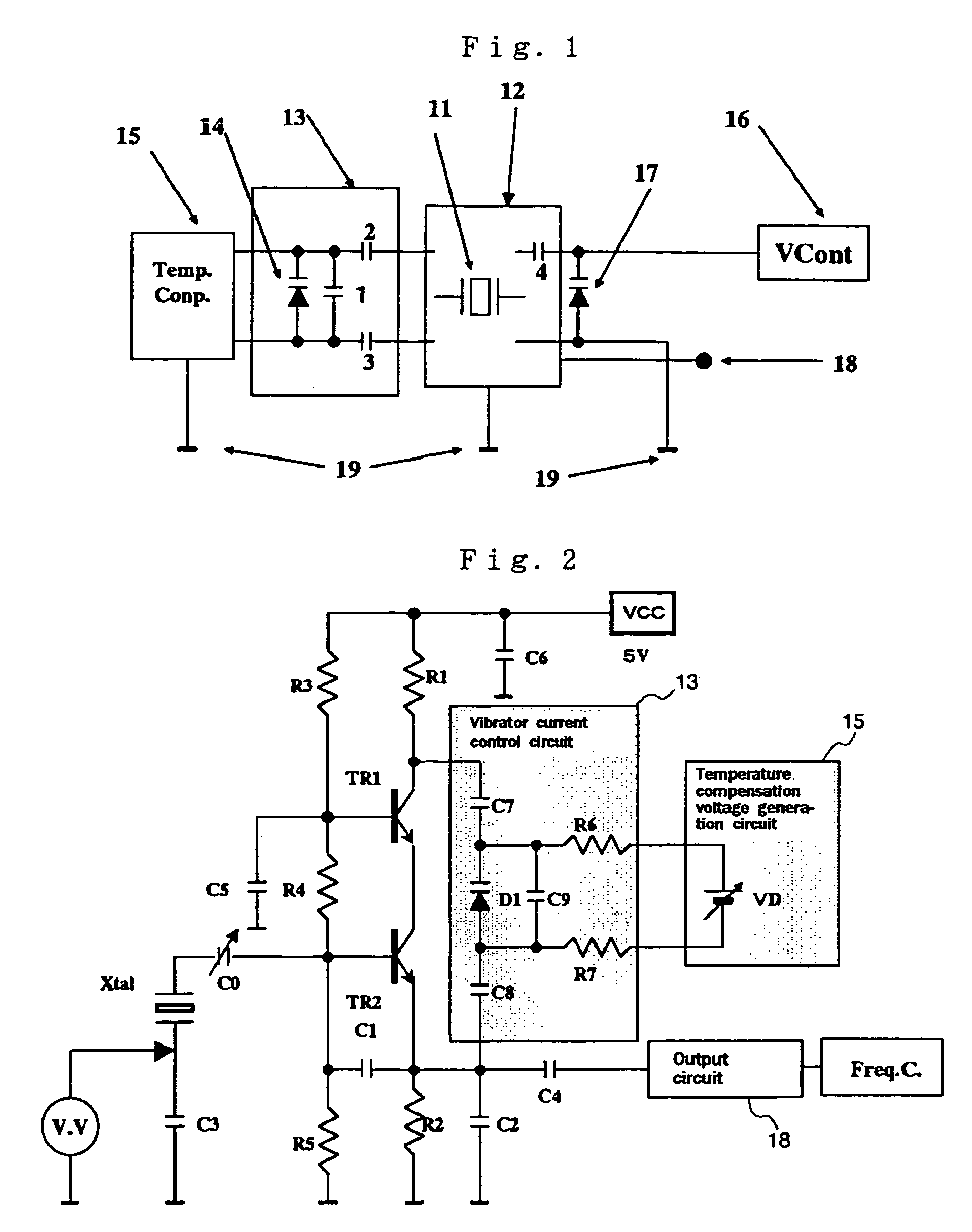
[0033]According to the above aspect of the invention, the vibrator current is controlled to compensate for the temperature characteristics. Therefore, an oscillator having two or more load capacitance variable functions can obtain a large variable range, and at the same time, can obtain high temperature stability without interfering with the mutual variable ranges.
[0039]According to the present aspect, as the reactance element that changes the oscillation frequency is further inserted, the oscillation frequency can be changed in a simple circuit configuration.
[0042]According to the present aspect, the variable reactance element is used that can optionally change the reactance element like the variable trimmer. Therefore, the oscillation frequency can be easily controlled externally.
[0044]According to the present aspect, the vibrator current controller comprises the correction variable capacitance diode. Therefore, it is possible to correct for the compensation distortion generated by changing the load capacitance, thereby to further decrease the frequency distortion relative to the application voltage.

Problems solved by technology

These functions necessarily interfere with the variable ranges.

Method used


Image

  • Crystal oscillator with temperature compensated through a vibrator current control circuit
  • Crystal oscillator with temperature compensated through a vibrator current control circuit
  • Crystal oscillator with temperature compensated through a vibrator current control circuit

Examples


Embodiment Construction

[0077]Embodiments according to the present invention will be explained in detail with reference to the drawings. Unless specified otherwise, configuration elements, kinds, combinations, shapes, and their relative positions that are described in the embodiments do not limit the range of the present invention, and they are simple explanatory examples.

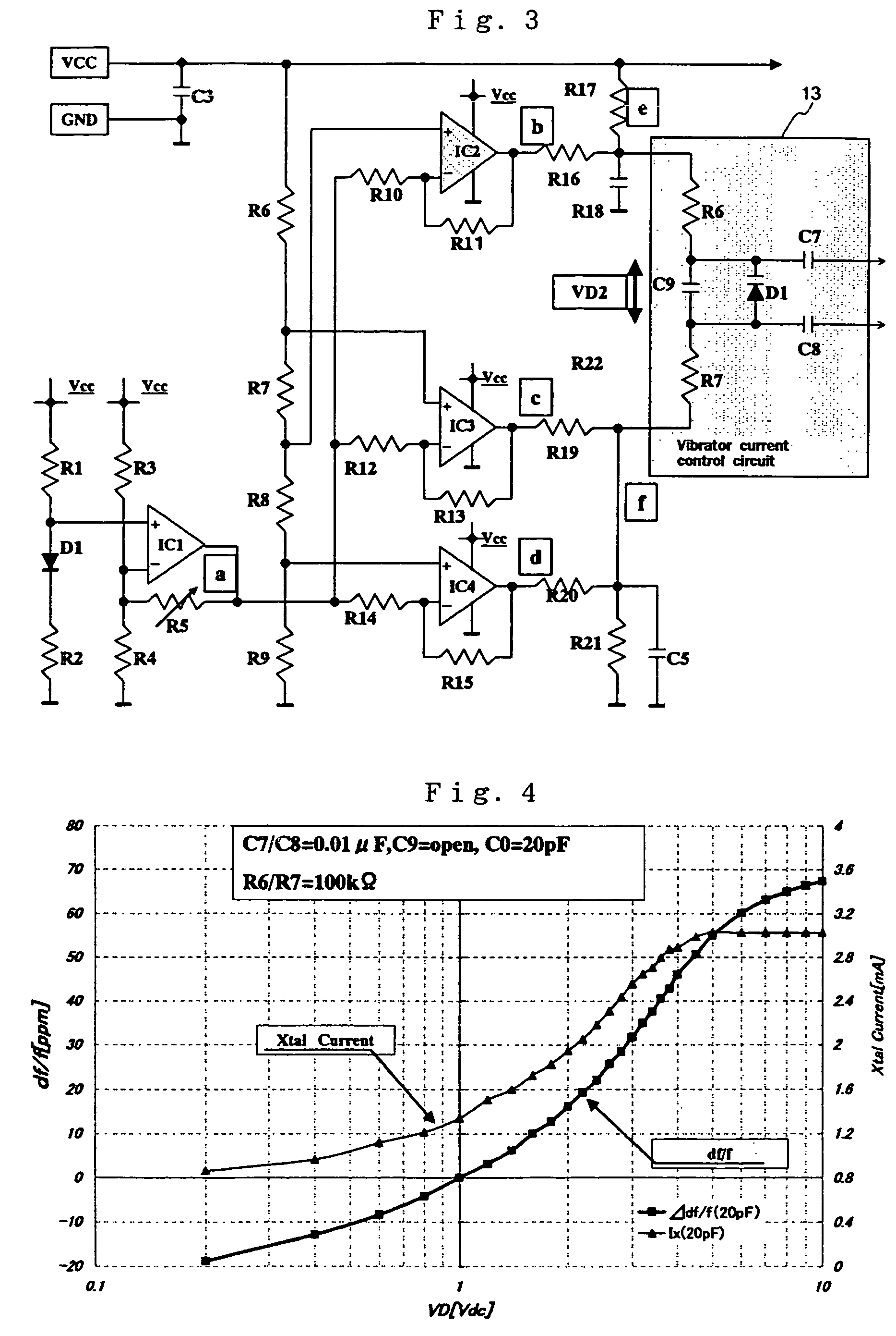
[0078]In general, stress and distortion of crystal of a crystal vibrator have a nonlinear relationship. Therefore, it is confirmed that the resonance frequency changes as follows according to the vibrator current. …⁢⁢Δ⁢⁢ff=K⁢⁢i2[0079]i: Vibrator current[0080]K: Proper constant determined by cut, vibration mode, electrode size, etc.

[0081]As a method for controlling the vibrator current at the oscillation time, an AGC circuit is added to a part of high stability crystal oscillators (OCXO) to improve the aging. However, this method involves complexity in the circuit and is not practical.

[0082]In the present example, a circuit described in Ja...


PUM


Abstract

The invention provides a temperature compensated crystal oscillator that can obtain a large variable range and that can obtain high temperature stability. This temperature compensation system employs a configuration comprising a oscillation circuit 12 including a crystal vibrator 11 having a piezoelectric element excited in a given frequency and an oscillation amplifier that excites the piezoelectric element by flowing a current to the piezoelectric element, a vibrator current control circuit 13 that controls the current of the crystal vibrator, a temperature compensation voltage generation circuit 15 that compensates for temperature characteristics of the crystal vibrator 11, and an external variable capacitance diode 17 that changes the oscillation frequency of the oscillation circuit 12 using an external variable voltage controller 16. The vibrator current control circuit 13 comprises a variable capacitance diode 14 that controls the vibrator current, and capacitors 1 to 3.

Description

BACKGROUND OF THE INVENTION[0001]1. Field of the Invention[0002]The present invention relates to a temperature compensated crystal oscillator. Particularly, the present invention relates to a temperature compensation method for a crystal oscillator that is used as a reference frequency in a mobile communication and a satellite communication etc.[0003]2. Description of the Related Art[0004]In recent years, the utilization range of the land mobile communication as represented by portable telephones is expanding steadily. Along this development, the portable telephones are also spreading rapidly, and are involving severe technical development competitions. Crystal oscillators that are used in the portable telephones are also required to have higher performance at low cost in small sizes. The oscillation frequency of the crystal vibrator changes in a cubic curve versus a change in the environmental temperature, as shown in FIG. 23. In order to obtain high stability, an oscillation circu...

Claims


Application Information

Patent Timeline
Patent Type & Authority Patents(United States)
IPC IPC(8): H03B5/32H03B5/04H03L1/02
CPCH03L1/028H03L1/023
Inventor SATOH, TOMIO
Owner SEIKO EPSON CORP
Why Eureka
Try Eureka