
Passive magnetic radome

a passive magnetic and radome technology, applied in the field of radomes, can solve the problems of affecting the performance of the radome, and reducing the service life of the radome, so as to achieve the effect of reducing the reflection

Inactive Publication Date: 2006-02-28
NORTH SOUTH HLDG
View PDF28 Cites 65 Cited by
  • Summary
  • Abstract
  • Description
  • Claims
  • Application Information

AI Technical Summary

Benefits of technology

[0015]Such an intrinsic impedance match requires the relative permeability value of the radome wall to be adjusted based upon the relative permittivity value of the wall and the relative permeability and permittivity values of the environment surrounding the radome. The intrinsic impedance match for a wave is dependant upon an angle of incidence at which the wave strikes the radome wall. Specifically, when the environment is air, an intrinsic impedance match can be established for a wave at normal incidence when the relative permeability and permittivity values of the wall are about equal. Calculations based upon the angle of incidence, the angle of transmittal, and the relative permeability and permittivity values for the wall and the environment can minimize the reflections occurring at any particular angle of incidence.

Problems solved by technology

Unfortunately, dielectric frames have numerous drawbacks.
Solid laminate designs can be cost effective for smaller radomes, but are generally unsuitable for larger ones.
However, in practice, conventional radomes are inherently lossy and are narrowbanded.
Moreover, loss generally increases with angle of incidence.
Unfortunately, such a radome transmits electromagnetic waves with minimal loss only over a narrow frequency band about a center frequency.

Method used


Image

  • Passive magnetic radome
  • Passive magnetic radome
  • Passive magnetic radome

Examples


Embodiment Construction

[0035]The invention disclosed herein provides a low loss broadband radome that includes walls having a relative permeability lur greater than one and methods for forming the same. Materials used in the construction of conventional radomes vary depending on the radome type. Conventional radomes provide dome walls made of dielectric materials having relative permeability μr of nearly 1.

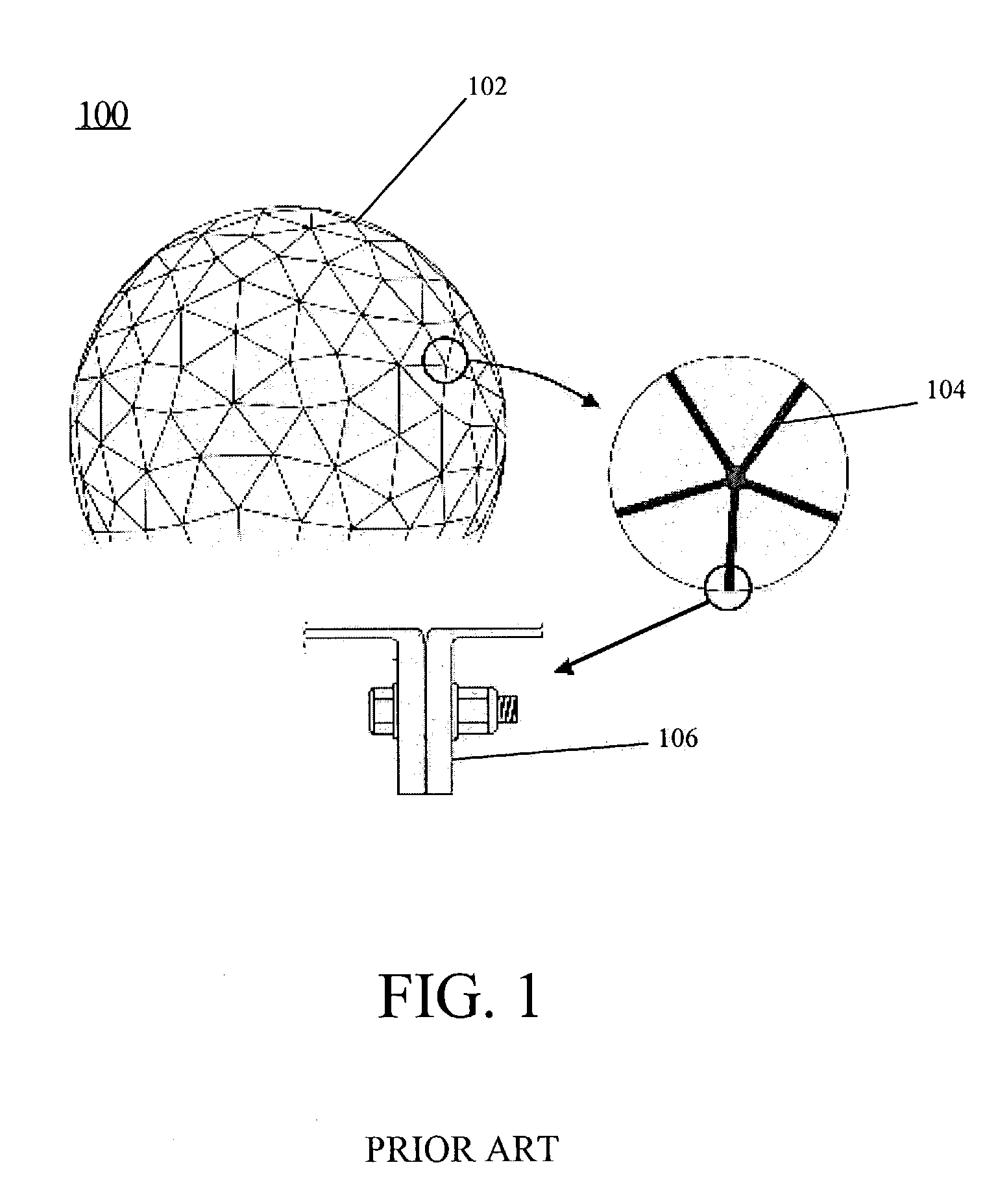
[0036]FIG. 1 is a schematic diagram illustrating a system 100 including a prior art space frame radome. System 100 illustrates a space frame radome 102, a magnified view of a radome frame 104, and a side view of a panel flange 106 used to connect adjacent frame panels.

[0037]In its simplest form, a space frame radome 102 utilizes a triangular patterned frame covered by a thin membrane material (not shown) forming one dome wall. The material forming the radome frame 104 can be aluminum, steel, or a dielectric, such as fiberglass. When a dielectric material is used to form a radome frame 104, inductive cir...


PUM


Abstract

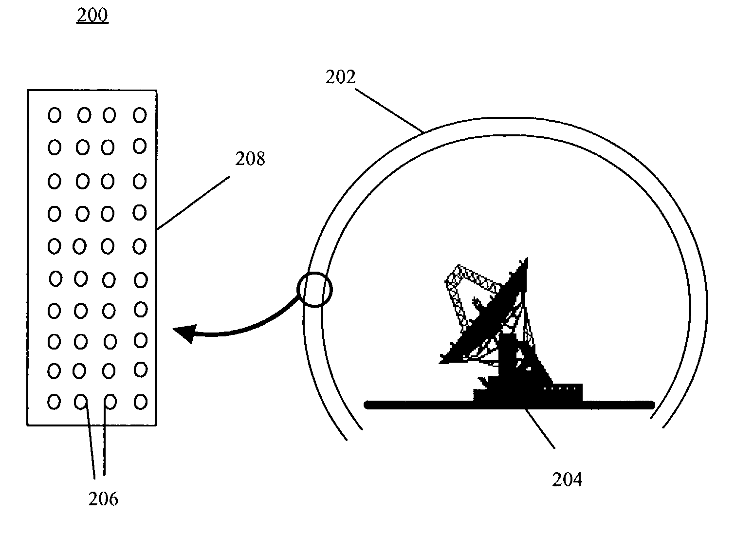
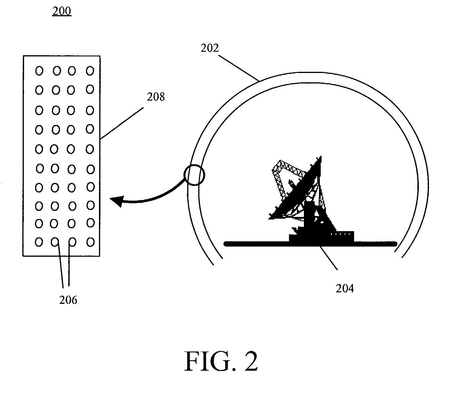
A radome (202) includes a dome wall (208) formed from a dielectric material wherein at least a portion of the dielectric material includes a plurality of magnetic particles (206). Radomes according to the invention can form dome walls of variable thickness, yet still have high radiation efficiency across a wide frequency band. Magnetic radomes utilize dielectrics including magnetic particles (206) to match the impedances between medium boundaries, such as an air to dome boundary.

Description

BACKGROUND OF THE INVENTION[0001]1. Statement of the Technical Field[0002]The present invention relates to the field of radomes, and more particularly to low loss broadband radomes.[0003]2. Description Of The Related Art[0004]Radomes are dome-like shells that are substantially transparent to radio frequency radiation. Functionally, radomes can be used to protect enclosed electromagnetic devices, such as antennas, from environmental conditions such as wind, solar loading, ice, and snow. Conventional radome types include sandwich, space frame, solid laminate, and air supported.[0005]Radomes can sometimes form very large domes for protecting large electromagnetic devices. For example, a space frame radome installed at Mt. Hebo in 1966 as part of the ballistic missile early warning system, had a diameter of 140 feet. Manufacturing and transportation considerations necessitate that large radomes be constructed in segments, often referred to as panels. One technique for connecting adjacen...

Claims


Application Information

Patent Timeline
IPC IPC(8): H01Q1/42
CPCH01Q15/0086H01Q1/42
Inventor DELGADO, HERIBERTO JOSEKILLEN, WILLIAM D.
Owner NORTH SOUTH HLDG
Learn More