Illuminating device and projector using it and built-in display unit

a technology of illumination device and projector, which is applied in the field of illumination optical system, can solve the problems of increasing the size of the prism, the motor or the like, the number of surfaces, and the need for a large rotation torque, and achieves the effect of reducing wind resistance and noise, simplifying the configuration of the electronic circuit, and reducing the number of surfaces

Inactive Publication Date: 2006-02-28
PANASONIC CORP
View PDF25 Cites 10 Cited by
  • Summary
  • Abstract
  • Description
  • Claims
  • Application Information

AI Technical Summary

Benefits of technology

[0004]Therefore, with the foregoing in mind, it is an object of the present invention to provide an illumination optical system that can achieve the improvement in scanning linearity and the reductions in wind resistance, cost, power consumption and noise, a projection video system, and an integral-type video display.
[0014]According to the illumination optical system of the present invention, the optical scanner or the combined optical scanner can provide favorable scanning linearity, which simplifies the configuration of an electronic circuit that constitutes the projection video system. Moreover, since the illumination optical system can achieve reduction both in wind resistance and noise, a smaller rotation torque is needed to rotate the optical scanner or the combined optical scanner. Therefore, they can be driven by a small motor, resulting in low cost and low power consumption. Thus, the present invention can provide an illumination optical system that can achieve good scanning linearity and the reductions in wind resistance, cost, power consumption and noise, a projection video system, and an integral-type video display.

Problems solved by technology

Therefore, an increase in the number of surfaces inevitably leads to an increase in size of the prism.
Moreover, to rotate a large prism, a motor or the like, acting as a rotation system, requires a large rotation torque.
These bring about a rise in the cost and in the power consumption.
In addition, the occurrence of wind resistance causes noise, which becomes a major obstacle to showing pictures.

Method used


Image

  • Illuminating device and projector using it and built-in display unit
  • Illuminating device and projector using it and built-in display unit
  • Illuminating device and projector using it and built-in display unit

Examples


embodiment 1

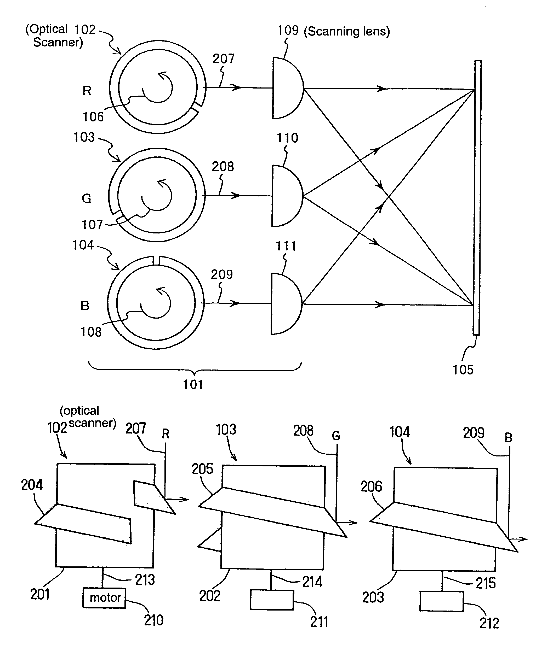
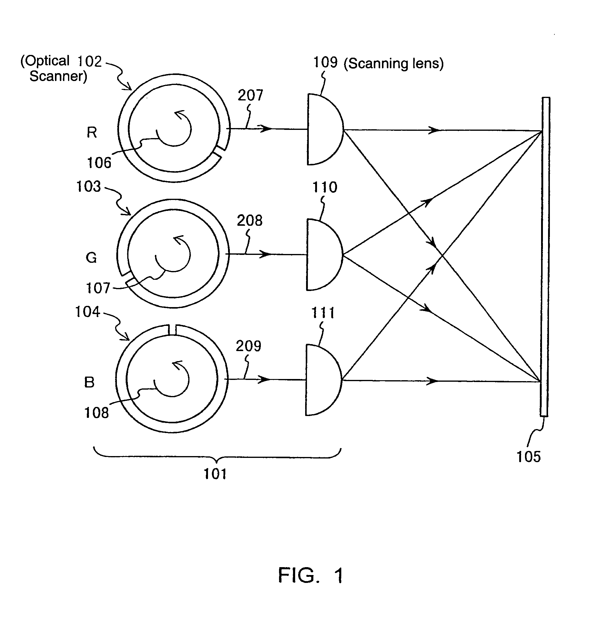
[0027]FIG. 1 is an elevation view showing an illumination optical system 101 of Embodiment 1 of the present invention that illuminates a region 105 to be illuminated by sequentially scanning the region 105 with a plurality of colors of light. An optical scanner 102 for scanning red light 207, an optical scanner 103 for scanning green light 208, and an optical scanner 104 for scanning blue light 209 are rotated by rotation systems (not shown) in the directions of arrows 106, 107 and 108, respectively. The red, green and blue light thus scanned are magnified in the direction of the width of the region 105 through the respective scanning lenses 109, 110 and 111, and at the same time, they scan the region 105 vertically with respect to the drawing sheet for illumination.

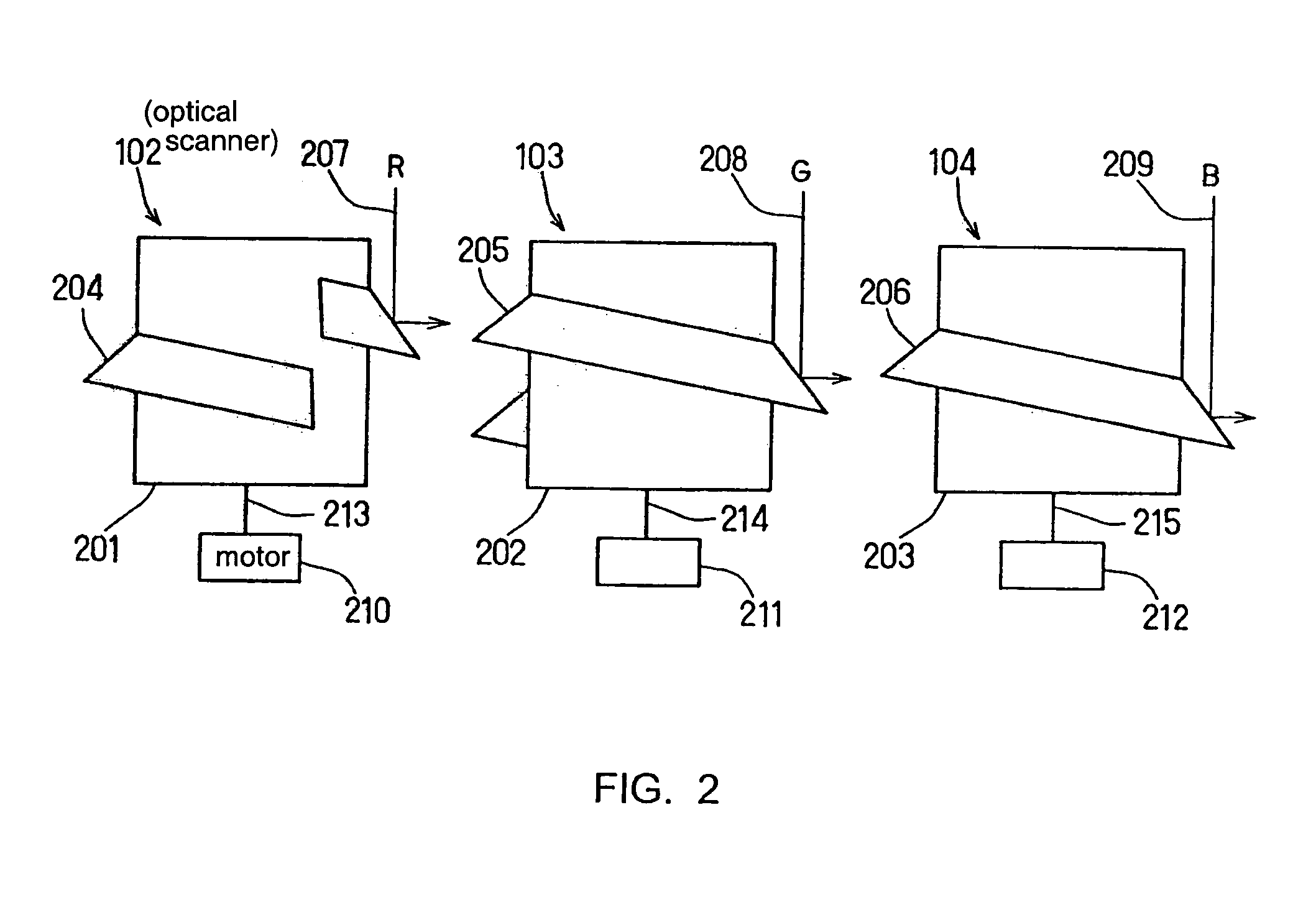
[0028]FIG. 2 is a front view showing the configurations of the optical scanners 102, 103 and 104 in FIG. 1. Reflecting surfaces 204, 205 and 206, each having a collar shape, are formed around cylindrical rotating bodies ...

embodiment 2

[0036]FIG. 3 is a cross-sectional view showing an illumination optical system 301 of Embodiment 2 of the present invention that illuminates a region 105 to be illuminated by sequentially scanning the region 105 with a plurality of colors of light.

[0037]A combined optical scanner 302 has the same configuration as that obtained when the optical scanners 102, 103 and 104 of Embodiment 1 are connected coaxially in the direction of the rotation axis. The combined optical scanner 302 is rotated around a rotation axis 310 by a motor 303, acting as a rotation system. The combined optical scanner 302 includes a cylindrical rotating body 311 having a plurality of reflecting surfaces 304, 305 and 306 on its side face. Each of the reflecting surfaces 304, 305 and 306 is defined by the path traced by a segment that tilts at a predetermined angle (e.g., 45 degrees) with respect to the rotation axis and moves along the rotation axis while rotating around the same. Moreover, the three reflecting su...

embodiment 3

[0044]FIG. 4 is a front view showing an illumination optical system 401 of Embodiment 3 of the present invention that illuminates a region 105 to be illuminated by sequentially scanning the region 105 with a plurality of colors of light, and FIG. 5 is a cross-sectional view thereof.

[0045]A combined optical scanner 402 is rotated by a motor 303, acting as a rotation system. The combined optical scanner 402 includes a cylindrical rotating body 407 having three dichroic mirror surfaces 403, 404 and 405 on its side face. Each of the dichroic mirror surfaces is defined by the path traced by a segment that tilts at a predetermined angle (e.g., 45 degrees) with respect to a rotation axis 310 and moves along the rotation axis while rotating around the same. Moreover, the three dichroic mirror surfaces 403, 404 and 405 are formed integrally with the rotating body 407 so that each of them has a predetermined phase difference in the rotational direction, i.e., they are shifted relative to one ...


PUM


Abstract

An illuminating device comprising a light source for emitting a plurality of light beams (207, 208, 209) of different colors, a plurality of rotating beam scanners (102, 103, 104) and a plurality of scanning lenses (109, 110, 111). The beam scanners have spiral reflection surfaces (102, 103, 204) formed on the outer peripheries of cylindrical bodies, Each colored light beam is shone onto each reflection surface from a direction parallel to a rotating axis, and magnified by each scanning lens after reflected to scan an illuminated area with a plurality of beams of different colors one after another. Accordingly, the illuminating device can enhance scanning linearity, reduce noise due to a minimal windage loss, and decrease costs and power consumption.

Description

TECHNICAL FIELD[0001]The present invention relates to an illumination optical system that performs sequential scanning with a plurality of different colors of light, a projection video system using the illumination optical system, and an integral-type video display using the projection video system.BACKGROUND ART[0002]An apparatus for magnifying and projecting an image by sequentially scanning a light valve with a plurality of different colors of light has been known from JP 6(1994)-319148 A. The apparatus includes first, second and third polygonal prisms that are arranged coaxially and shifted relative to one another by a rotation angle of 30 degrees with respect to the rotation axis. The polygonal prisms are rotated, so that the different colors of light entering the respective prisms are refracted to scan the light valve sequentially.[0003]As described above, the rotating polygonal prism is used to deflect light incident thereon by refraction. Thus, scanning linearity depends on ...

Claims


Application Information

Patent Timeline
Patent Type & Authority Patents(United States)
IPC IPC(8): H04N5/74G02B26/10G02B27/14H04N9/31
CPCG02B26/10G02B27/104G02B27/1053H04N9/3197H04N9/3117H04N9/3129G02B27/145G02B27/18
Inventor YAMAMOTO, YOSHIHARUYOSHIKAWA, MOTONOBU
Owner PANASONIC CORP
Why Eureka
Try Eureka