Driving circuit for DC/DC converter

a driving circuit and converter technology, applied in the direction of electric variable regulation, process and machine control, instruments, etc., can solve the problems of increasing the complicacy of manufacturing, increasing the cost of the driver, and significant switching loss of the switch, so as to increase the switching speed of the low-side switch and the high-side switch, simple structure, and large source

Active Publication Date: 2006-02-28
DELTA ELECTRONICS INC
View PDF5 Cites 34 Cited by
  • Summary
  • Abstract
  • Description
  • Claims
  • Application Information

AI Technical Summary

Benefits of technology

[0007]It is further an object of the present invention to achieve an adjustable dead time setting function to avoid the potential cross conduction problem between the high-side and low-side switches.
[0008]It is further another an object of the present invention to have a large source and a sink current ability to increase the switching speed of the low-side switch and the high-side switch.
[0009]It is additional an object of the present invention to achieve a driving circuit for DC / DC converter with a simple structure and very low cost driving method.

Problems solved by technology

Several disadvantages occur due to the employment of the high voltage rated switches M1 and M2.
Firstly, switching loss of these switches is significant especially at a high switching frequency.
Secondly, the switches M1 and M2 are packaged into the driver IC, which increases the complicacy of the manufacturing.
Thirdly, these high voltage rated switches increase the cost of the driver.
In most of the driver ICs, the ability of the source current and sink current is limited, which will slow the turning on and turning off speed of the switch component in a larger power converter and will decrease the efficiency of the converter.

Method used


Image

  • Driving circuit for DC/DC converter
  • Driving circuit for DC/DC converter
  • Driving circuit for DC/DC converter

Examples


Embodiment Construction

[0024]The present invention will now be described more specifically with reference to the following embodiments. It is to be noted that the following descriptions of preferred embodiments of this invention are presented herein for purpose of illustration and description only; it is not intended to be exhaustive or to be limited to the precise form disclosed.

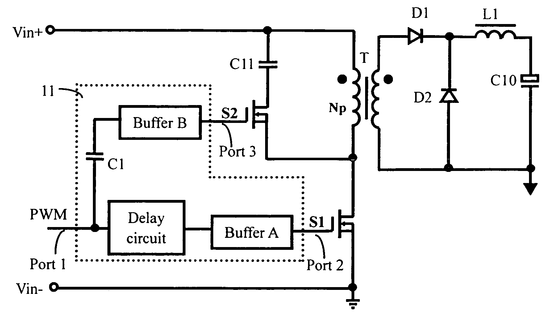
[0025]This driving circuit of the present invention is used for driving a switch-bridge of a DC-DC converter, which can be an active clamp forward converter, an active clamp flyback converter, an active clamp forward-flyback converter, a boost converter, or a boost half-bridge converter. The switch-bridge of the DC-DC converter is composed of a main switch (a low-side switch) and an active switch (a high-side switch) connected in series. The active switch operates in complementary to the main switch. Hereafter, for example, a driving circuit applied to an active clamp forward converter will be illustrated in detail.

[0026]Referrin...


PUM


Abstract

A driving circuit comprises an input terminal receiving an input of a PWM signal, a first output terminal connected to a main switch for outputting a low-side driving signal, a second output terminal connected to an active switch for outputting a high-side driving signal, a first branch having a voltage level shifting capacitor and a first buffer connected in series between the input terminal and the second output terminal; and a second branch having a delay circuit and a second buffer connected in series between the input terminal and the first output terminal. When the input of the PWM signal turns from a low level to a high level, the voltage level shifting capacitor transmits the input of PWM signal to the first buffer for turning off the active switch and then triggering the second buffer to turn on the main switch with a short time delay.

Description

FIELD OF THE INVENTION[0001]The present invention relates to a power supply system and more particularly to a driving circuit for DC / DC converter.BACKGROUND OF THE INVENTION[0002]A high-side and low-side driver is widely applied to drive the switch-bridge of bridge type converters, such as active clamp forward converter, half-bridge converter and full-bridge converter. FIG. 1 shows a conventional configuration of an active clamp forward converter with a driving IC. In this converter, a low-side switch S1 (main switch) is employed in the primary side of the transformer T, and an active clamp branch is connected in parallel with the primary winding of the transformer T. The active clamp branch includes a high-side switch (active switch) S2 and a clamping capacitor C11 connected in series. The low-side switch S1 and the high-side switch S2 operating in complementary form a switch-bridge, and a high-side and low-side driving IC 1 is employed to drive the switch-bridge.[0003]At present, ...

Claims


Application Information

Patent Timeline
Patent Type & Authority Patents(United States)
IPC IPC(8): H02M3/335H02H7/122
CPCH02M1/08H02M1/34Y02B70/1491H02M2001/342H02M3/335Y02B70/10H02M1/342
Inventor JIN, BINKE, ZHONGWEIXIONG, YAHONGZHANG, ALPHA J.
Owner DELTA ELECTRONICS INC
Why Eureka
Try Eureka