Qualifying available reverse link coding rates from access channel power setting

Active Publication Date: 2006-02-28
IPR LICENSING INC
View PDF8 Cites 70 Cited by
  • Summary
  • Abstract
  • Description
  • Claims
  • Application Information

AI Technical Summary

Benefits of technology

[0009]Upon receipt of these two pieces of information, the forward path loss estimate as calculated by the field unit and the existing field unit power amplifier value, the base station can then determine the amount of excess power available at the field unit. This excess power difference is indicative of the amount of dynamic range available in the transmit power amplifier in the particular field unit. With this information, the base station can then make a determination as to whether coding rates which require a higher dynamic range will be acceptable for use by the particular field unit. If, for example, a relatively large amount of excess power margin appears to be available at the field unit, i.

Problems solved by technology

If they do not, channel interference increases.
While such codes do provide increased performance in terms of lower bit err

Method used


Image

  • Qualifying available reverse link coding rates from access channel power setting
  • Qualifying available reverse link coding rates from access channel power setting
  • Qualifying available reverse link coding rates from access channel power setting

Examples


Example

1. System Architecture and Introduction

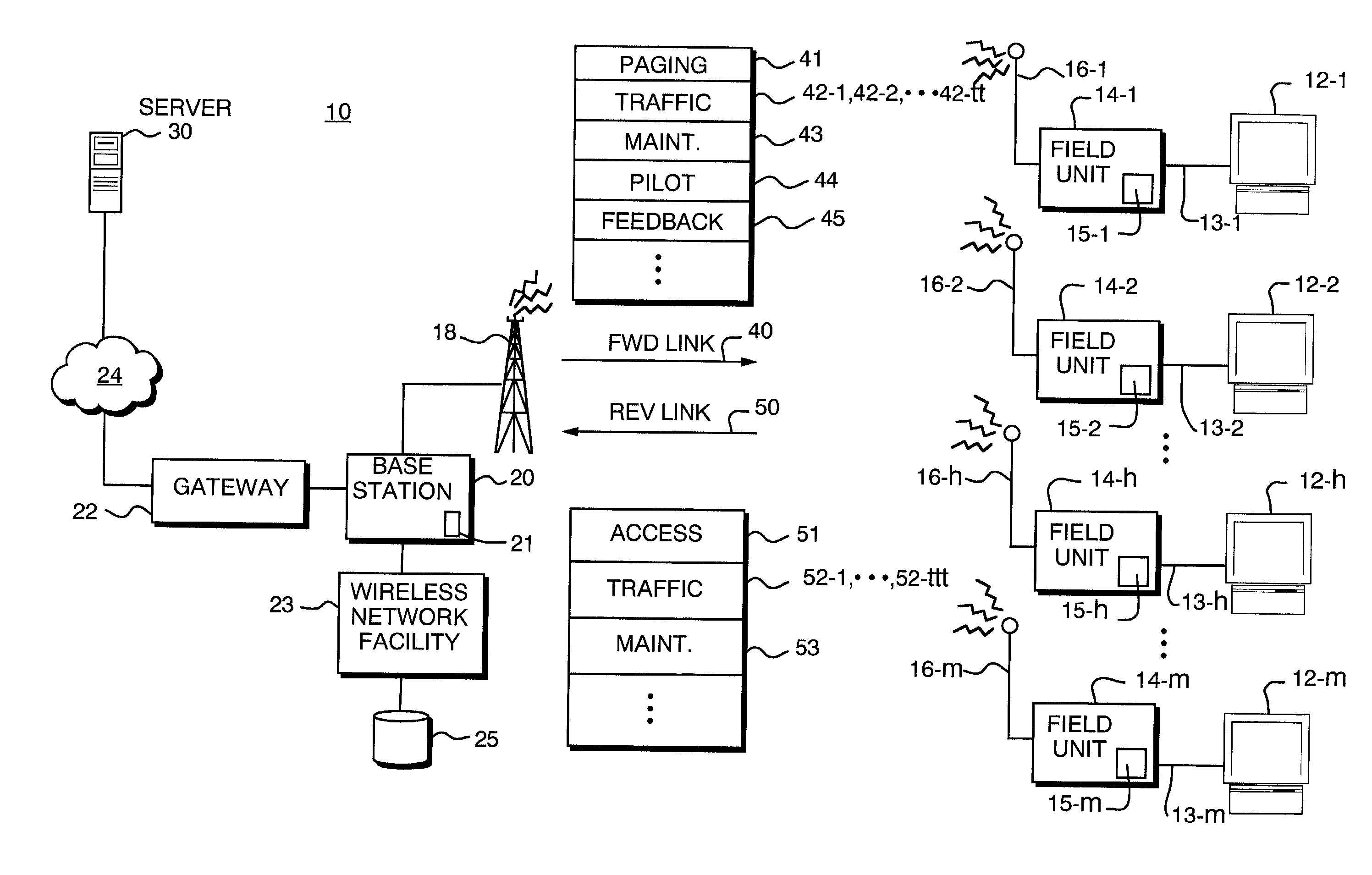
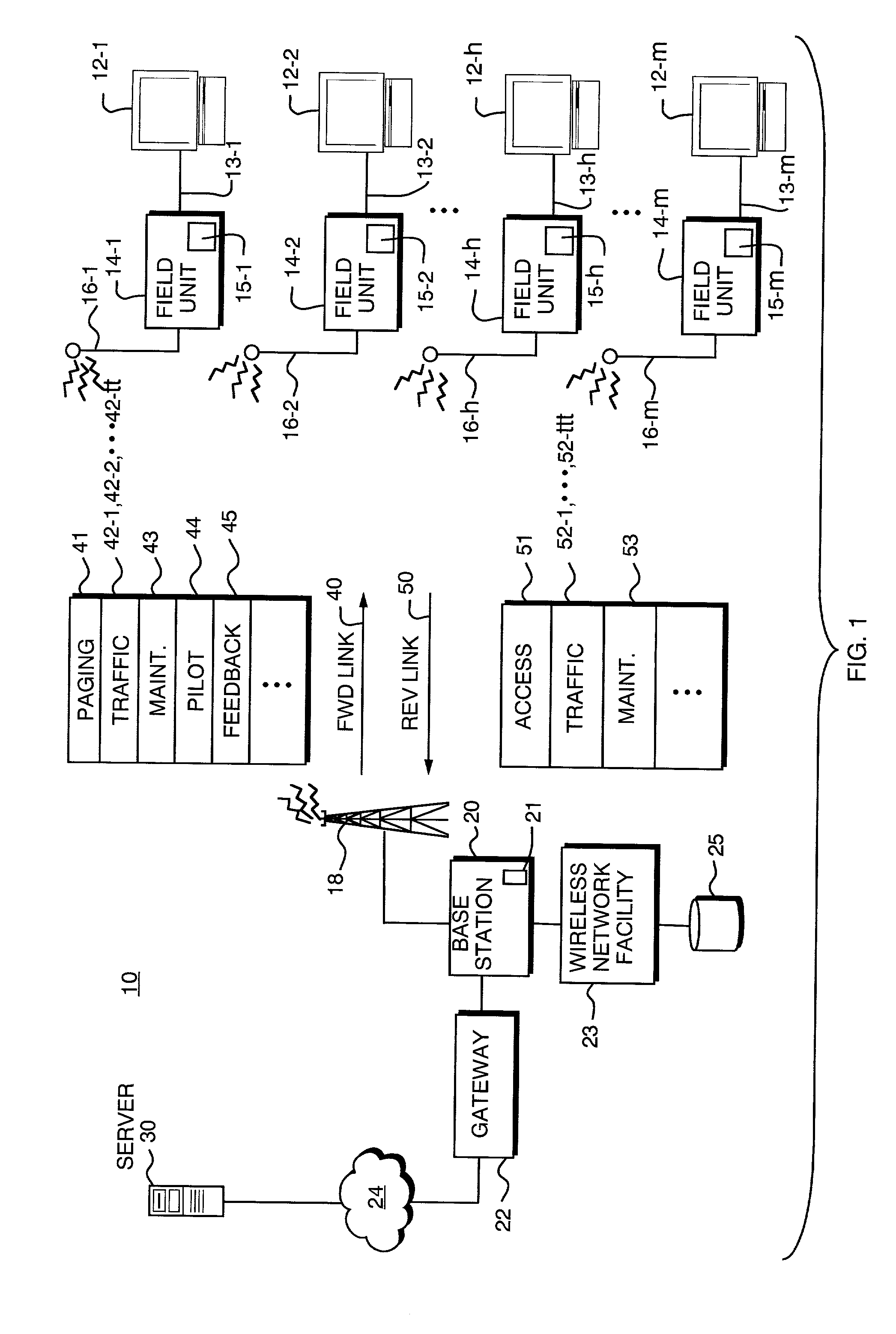
[0020]FIG. 1 is a block diagram illustrating a wireless communication system 10 supporting the transmission of data at different rates for particular users, depending upon observed channel conditions for each user. As in many wireless communication systems, users compete for wireless bandwidth allocation. Hence, it is desirable that the wireless communication 10 is optimized for data throughput and, in certain applications, hi-speed bursts of data throughput. Certain aspects of the present invention are based on the recognition that the data rates assigned to a field unit transmitting over a wireless channel can be controlled so that minimally interference with other field units using the same general wireless airspace is created. Specifically, a radio frequency (RF) path loss is determined by broadcasting Effective Radiated Power (ERP) information from a central base station 20. A remote field unit 24 receives this ERP information and also det...


PUM


Abstract

Data rate allocation decisions are made for a communications channel, such as a wireless reverse link connection. A first parameter used in this determination is a path loss, which is determined by the following process. First, a message is sent from a first station to a second station, such as on a paging channel. The message indicates a forward Effective Radiated Power (ERP) of a pilot signal transmitted by the first station. The second station then determines the received signal strength of this pilot signal, taking into account receiver gains. The path loss can then be estimated by the second station as the difference between the forward ERP data value that it received and the detected received pilot power. The second station also then preferably determines a transmit power level when transmitting a message back to the first station. This transmit power level information is encoded as a digital data word together with the forward path loss information as calculated by the first station. Upon receipt of these two pieces of information by the first station, the forward path loss estimate as calculated by the second station, and the output power value of the second station, the first station can then determine the amount of excess power available at the field unit. This excess power difference is indicative of the amount of dynamic range available in the transmit power amplifier in the particular second station. With this information, the first station can then make a determination as to whether coding rates which require a higher dynamic range will be acceptable for use by the particular second station.

Description

FIELD OF THE INVENTION[0001]This invention relates generally to wireless communication systems, and more particularly to a technique for selecting from among several available data rate connections based upon observed conditions in digitally encoded radio channels.BACKGROUND OF THE INVENTION[0002]The first generation of personal wireless communication devices, such as cellular radio telephones, operated by allocating distinct individual radio carrier frequencies to each user. For example, in an Advanced Mobile Phone Service (AMPS) type cellular mobile telephone, two 30 kiloHertz (kHz) bandwidth channels are allocated to support full duplex audio communication between each subscriber unit and a base station. The signals within each such channel are modulated using analog techniques such as Frequency Modulation (FM).[0003]Later generation systems make use of digital modulation techniques in order to allow multiple users to access the same frequency spectrum at the same time. These tec...

Claims


Application Information

Patent Timeline
IPC IPC(8): H04B7/212H04B7/005H04L12/56
CPCH04W28/22H04W72/042H04W52/26H04J13/00H04W52/24H04W24/00H04W48/08Y02B60/50H04W72/23Y02D30/70H04W72/20H04W72/51H04J13/0003H04W72/0446H04L5/22H04W52/365H04W72/0466H04W72/0473
Inventor NELSON, JR., GEORGE RODNEYPROCTOR, JR., JAMES A.HOFFMANN, JOHN E.ROUPHAEL, ANTOINE J.
Owner IPR LICENSING INC
Why Eureka
Try Eureka