
Multistage pipeline bit conversion

a multi-stage pipeline and bit conversion technology, applied in the field of communication over networks, can solve the problem that old interface circuits b>160/b> cannot be readily adapted for use with the new standard

Active Publication Date: 2006-02-28
INTELLECTUAL VENTURES II
View PDF5 Cites 5 Cited by
  • Summary
  • Abstract
  • Description
  • Claims
  • Application Information

AI Technical Summary

Benefits of technology

[0010]The invention provides a system that converts words of pipelined data from a first data width to a smaller data width over a series of cycles. Converting data widths is often a by-product of transporting data over an optical network because of the limitations of fiber optic cables. The result of the conversion is that concatenation of the input data at the first data width is equal to concatenation of the output data at the smaller data width. The system has a pipeline control, a delay register, a combinor circuit, and output conduits.

Problems solved by technology

Old interface circuits 160 cannot be readily adapted for use with the new standard because both translations from the transport medium to the devices on the network and collision detection mechanisms function differently.

Method used


Image

  • Multistage pipeline bit conversion
  • Multistage pipeline bit conversion
  • Multistage pipeline bit conversion

Examples


Embodiment Construction

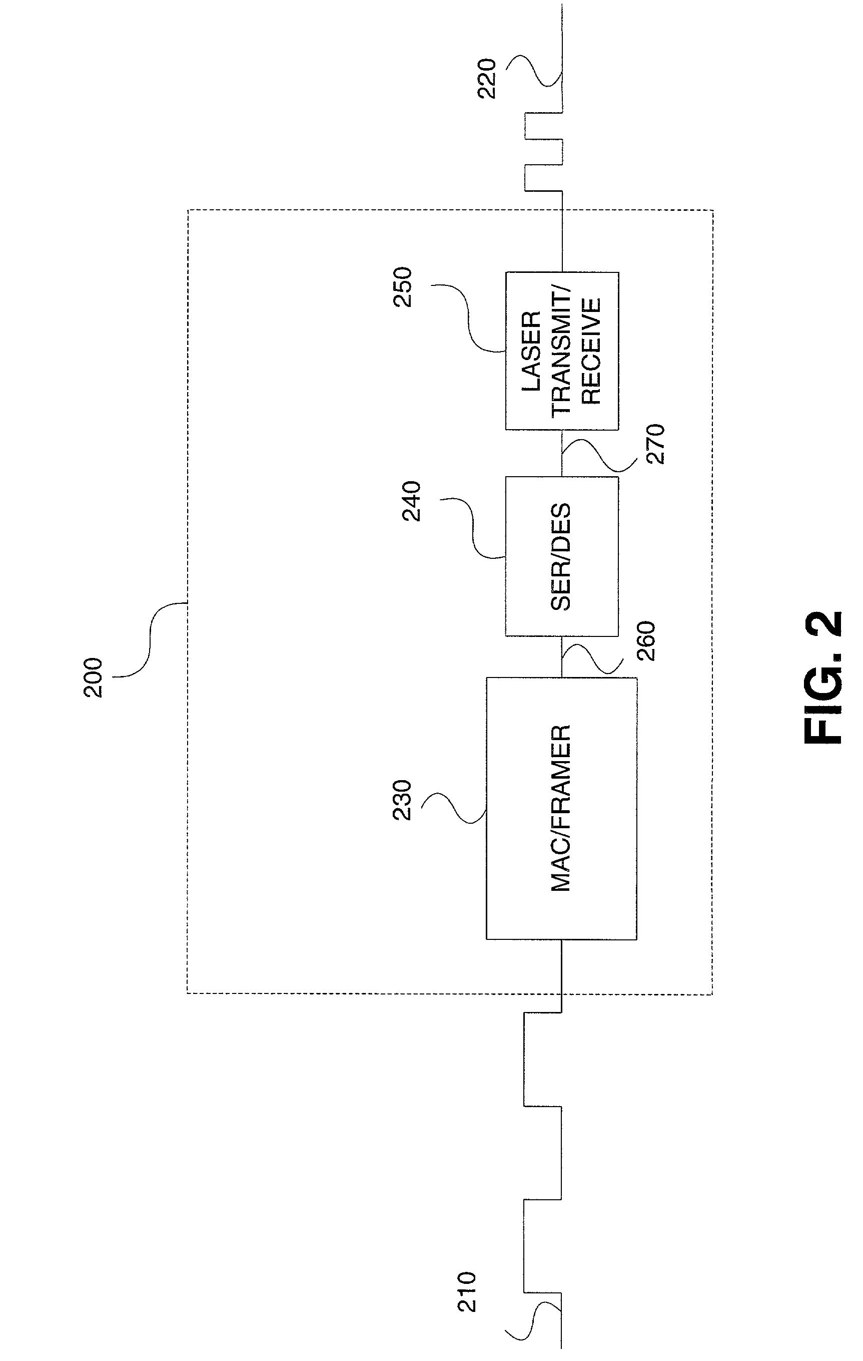
[0029]FIG. 2 shows an interface circuit 200 that allows devices to transmit information over optical network 110 by converting a 64-bit unencapsulated signal 210 at a first clock rate to an optical signal 220 at a second clock rate. Interface circuit 200 includes a MAC / framer circuit 230, a serializer / deserializer circuit 240, and a laser transmit / receive circuit 250.

[0030]During a transmit operation, MAC / framer circuit 230 receives 64-bit unencapsulated signal 210 from the device attempting to communicate data over optical network 110, encapsulates the data in accordance with Ethernet protocols, and prepares the data for transmission over optical network 110. An output signal 260 from MAC / framer circuit 230 is also 64 bits wide, but travels at an intermediate clock rate that is faster than 64-bit unencapsulated signal 210 and includes both the original data and the encapsulation information.

[0031]Serializer / deserializer circuit 240 transforms output signal 260 from a 64-bit paralle...


PUM


Abstract

A system and method that converts a series of input data words at a first data width to a series of output data words at a smaller data width. In order to achieve 10-Gigabit Ethernet over an optical network, data must be converted from 66-bit words to 64-bit words (the smaller data width) at a faster clock rate, such that the concatenation of the series of input data is equivalent to the concatenation of the series of output data. This is accomplished by shifting the input data such that it is either prefixed by zeros, suffixed by zeros, or both, depending on the stage of the progression of the series. The shifted data is then split up, with a portion of the data going into a delay register and another portion of the data either being output directly or combined with data previously stored in the delay register.

Description

BACKGROUND OF THE INVENTION[0001]1. Field of the Invention[0002]The invention relates generally to communication over networks, and more particularly to signal mapping prior to transmitting the signal over a network.[0003]2. Background of the Invention[0004]Electronic information is often shared through computer networks. These networks can vary in size from small networks of just a few devices sharing information to large-scale global networks, such as the Internet. Regardless of the size, there must be a mechanism in every network to transport information. Information in the form of electrical signals are often transported through copper cable; information in the form of optical signals are transported through fiber optic cables; and other electromagnetic waves can be transported through the air.[0005]FIG. 1 shows several devices connected together through an optical network 110. Optical networks have several advantages, including a large bandwidth, low susceptibility to interfere...

Claims


Application Information

Patent Timeline
Patent Type & Authority Patents(United States)
IPC IPC(8): G06F3/00
CPCH04L25/05
Inventor O'CONNOR, STEPHEN
Owner INTELLECTUAL VENTURES II
Features
  • Generate Ideas
  • Intellectual Property
  • Life Sciences
  • Materials
  • Tech Scout
  • Unparalleled Data Quality
  • Higher Quality Content
  • 60% Fewer Hallucinations
Learn More