Polarization splitting grating couplers

a grating coupler and polarization technology, applied in the field of polarization splitting grating couplers, can solve the problems of significant signal loss and distortion, random power transfer between the two polarizations, and the difficulty of connecting an optical signal from a fiber to a waveguide using a waveguide grating coupler

Active Publication Date: 2006-02-28
CISCO TECH INC
View PDF11 Cites 68 Cited by
  • Summary
  • Abstract
  • Description
  • Claims
  • Application Information

AI Technical Summary

Problems solved by technology

But there are difficulties in connecting an optical signal from a fiber to a waveguide using a waveguide grating coupler, due to differences in: cross sectional geometry, the number of optical modes and polarization characteristics.
But connecting an optical signal from a fiber to a waveguide can cause significant signal loss and distortion due to the typically different and incompatible polarization characteristics.
But in actual practice, imperfections or strains in the fiber cause random power transfer between the two polarizations.
The total power is thus divided between the two polarizations, and this may not be a problem in some applications, but in many situations, this can be a major problem.
In some cases, there can be a great deal of fluctuation and power transfer between the two polarizations.
Such random fluctuations can cause the power delivered on one polarization, to be close to zero, which would result in considerable loss of signal, if only that polarization is being received by a waveguide on a chip.
But a typical waveguide cannot usually propagate both of the modes, which would result in some signal loss in such a fiber to waveguide connection.
As a result of the differences in polarization characteristics between fibers and waveguides, it has been difficult to connect optical signals from one to the other.

Method used


Image

  • Polarization splitting grating couplers
  • Polarization splitting grating couplers
  • Polarization splitting grating couplers

Examples


Embodiment Construction

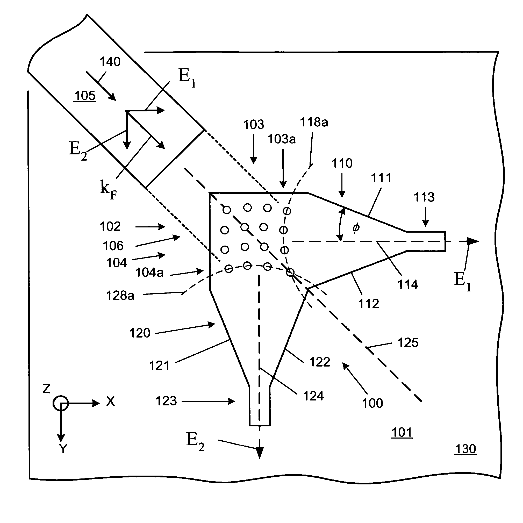
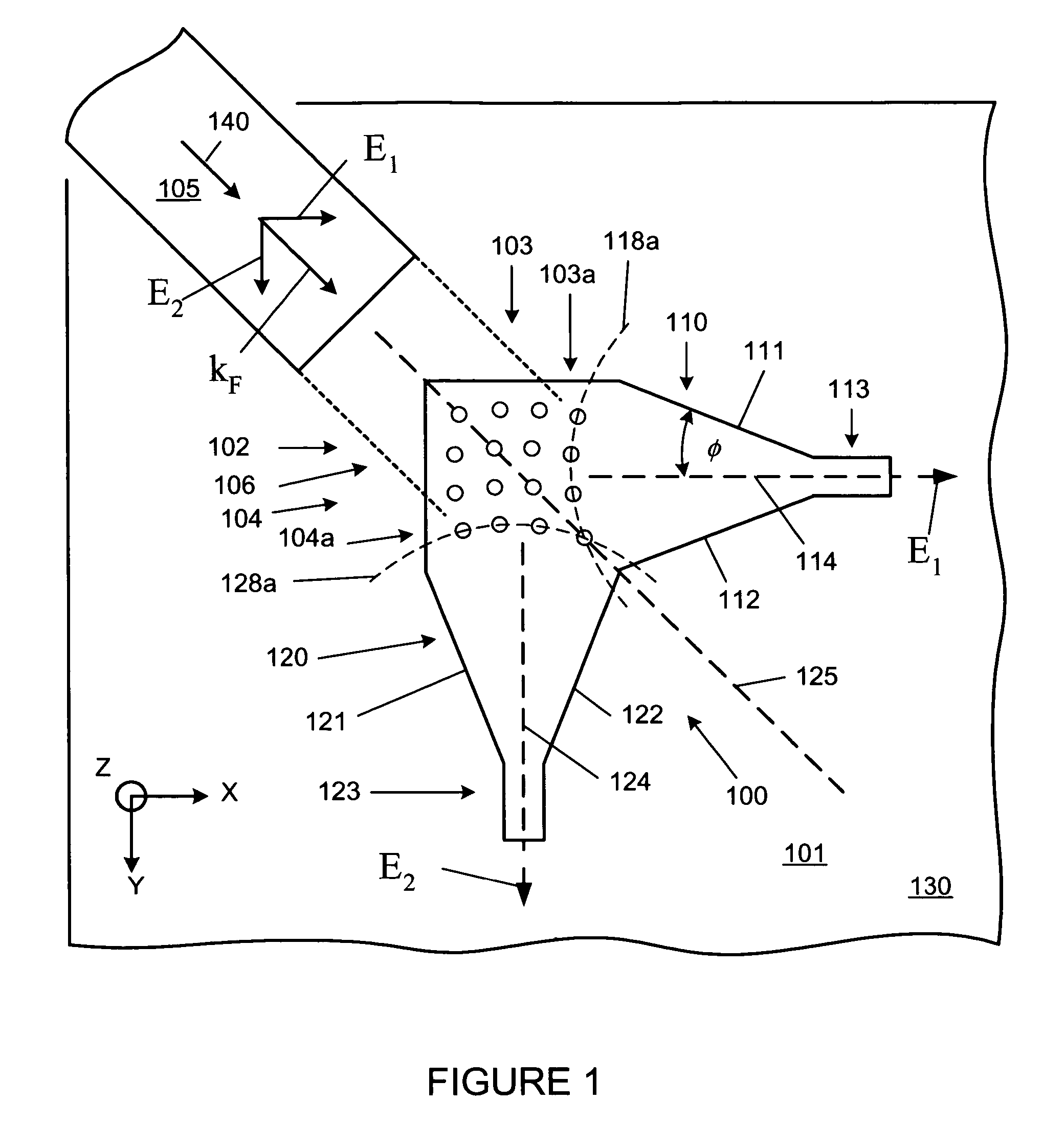
[0025]FIG. 1 is a top view of an integrated polarization splitting waveguide grating coupler, not to scale, according to one embodiment of the present invention. Polarization splitting grating coupler (herein “PSGC”) 100 is part of integrated circuit 101, which has been built on substrate 130. PSGC 100 connects light between optical element 105 and integrated circuit 101. In FIG. 1, optical element 105, such as an optical fiber, has been shown above and off to the side of integrated circuit 101 and thus is not intended to provide a figure of a system during operation. PSGC 100 includes cross grating 102, flared waveguides 110 and 120 and linear waveguides 113 and 123. Waveguides 113 and 123 connect optical signals to waveguides or other optical devices, not shown, on integrated circuit 101. The cross grating 102 includes many light scattering elements 106. The substrate 130 can be made of any of a variety of substrates such as: silicon, silicon on insulator (SOI), silicon on sapphir...


PUM


Abstract

A polarization splitting grating coupler (PSGC) connects an optical signal from an optical element, such as a fiber, to an optoelectronic integrated circuit. The PSGC separates a received optical signal into two orthogonal polarizations and directs the two polarizations to separate waveguides on an integrated circuit. Each of the two separated polarizations can then be processed, as needed for a particular application, by the integrated circuit. A PSGC can also operate in the reverse direction, and couple two optical signals from an integrated circuit to two respective orthogonal polarizations of one optical output signal sent off chip to an optical fiber.

Description

CROSS-REFERENCE TO RELATED APPLICATIONS[0001]This application claims priority from U.S. Provisional application No. 60 / 456,381 filed Mar. 21, 2003.FIELD OF THE INVENTION[0002]The present invention relates to an apparatus for facilitating the connection of optical signals from optical fibers to optoelectronic integrated circuits.BACKGROUND OF THE INVENTION[0003]Optical fibers have been widely used for the propagation of optical signals, especially to provide high speed communications links. Optical links using fiber optics have many advantages compared to electrical links: large bandwidth, high noise immunity, reduced power dissipation and minimal crosstalk. Optical signals carried by optical fibers are processed by a wide variety of optical and optoelectronic devices, including integrated circuits. Optical communications signals in optical fibers are typically in the 1.3 μm and 1.55 μm infrared wavelength bands. Optoelectronic integrated circuits made of silicon are highly desirable...

Claims


Application Information

Patent Timeline
Patent Type & Authority Patents(United States)
IPC IPC(8): G02B6/34G02B6/26G02B6/42G02B6/124G02B6/126G02B6/27
CPCG02B6/1228G02B6/124G02B6/126G02B6/30G02B6/34G02B6/2733G02B6/2726G02B2006/1213G02B6/2773G02B6/4214
Inventor GUNN, III, LAWRENCE C.PINGUET, THIERRY J.RATTIER, MAXIME J.WITZENS, JEREMY
Owner CISCO TECH INC
Why Eureka
Try Eureka