
Hot isostatic pressing apparatus

a technology pressing chamber, which is applied in the direction of auxillary shaping apparatus, shaping press, butter production, etc., can solve the problems of high treatment cost, long cycle time, and high utilization rate of hot isostatic pressing, and achieve the effect of efficiently reheating workpieces

Inactive Publication Date: 2006-03-07
KOBE STEEL LTD
View PDF9 Cites 15 Cited by
  • Summary
  • Abstract
  • Description
  • Claims
  • Application Information

AI Technical Summary

Benefits of technology

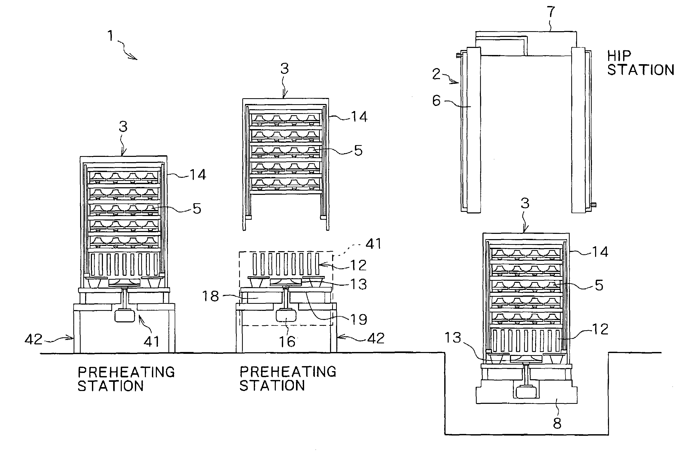
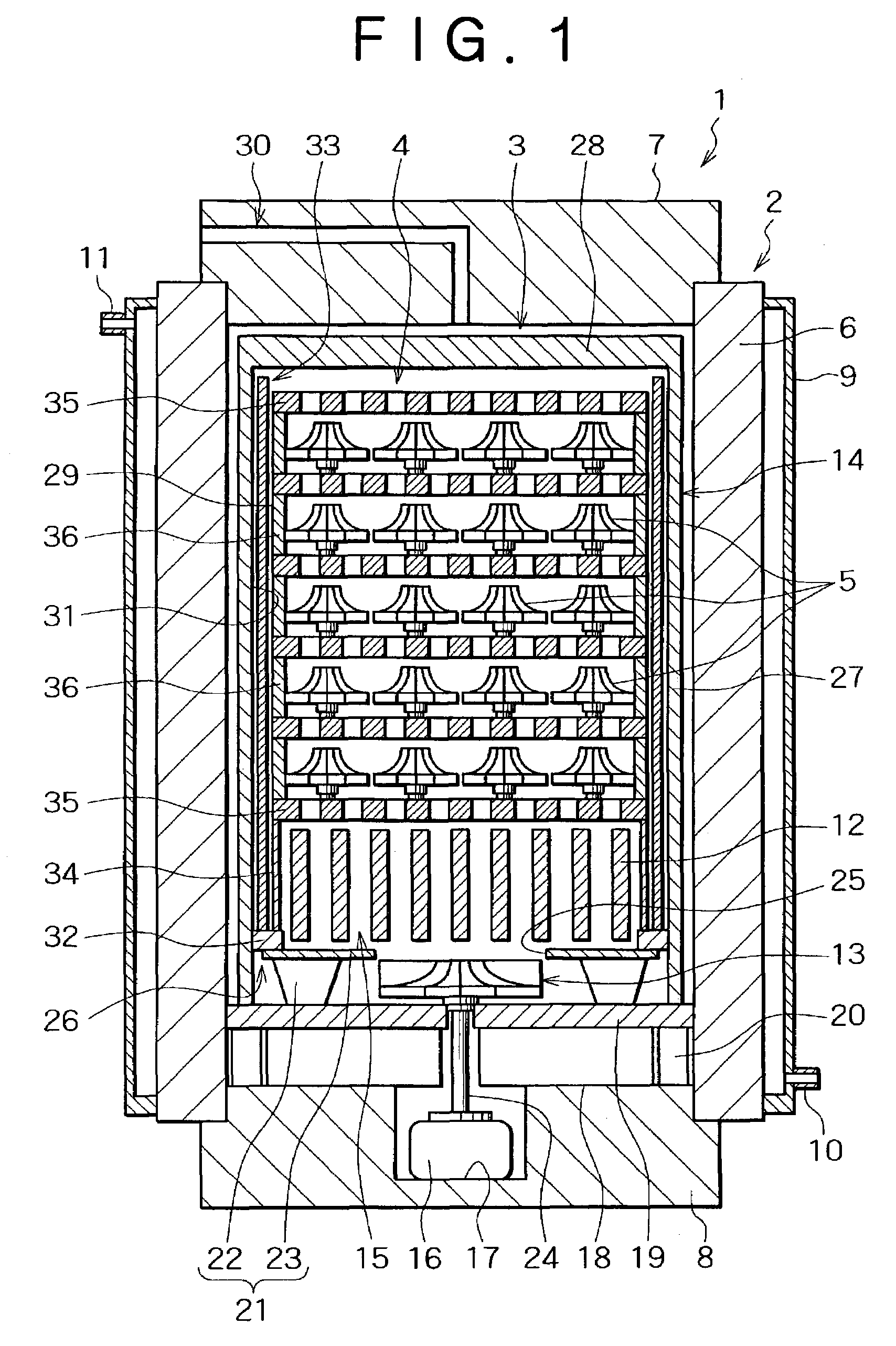
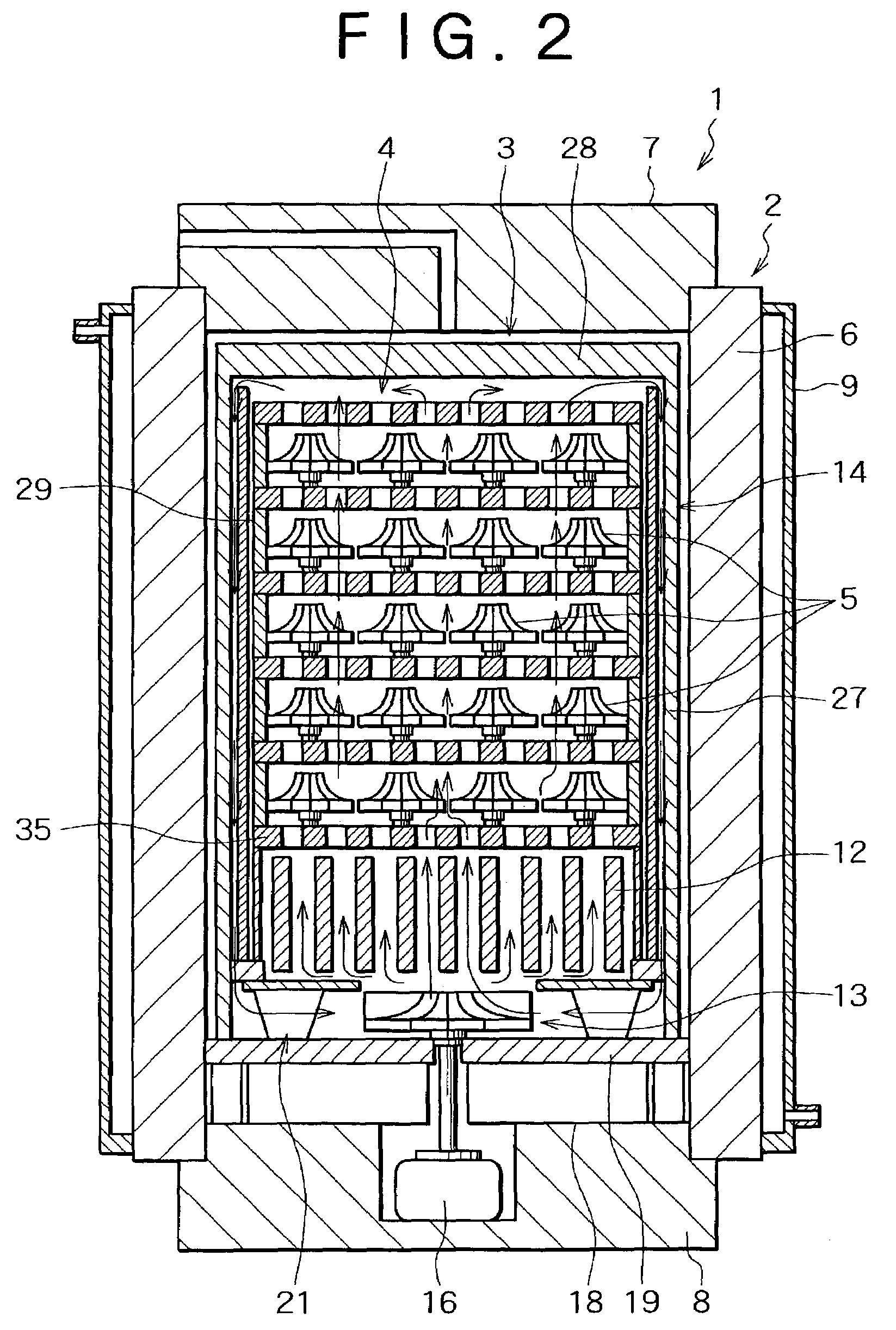
The present invention provides a hot isostatic pressing apparatus that can efficiently heat and press workpieces while minimizing temperature variations caused by the injection of a pressure medium gas. The apparatus includes a high-pressure vessel with a treatment chamber, a base heater, a fan, and a heat insulating structure. The heat insulating structure can be attached to and detached from the lower lid of the high-pressure vessel. The apparatus can also be equipped with a station outside the high-pressure vessel for preheating and cooling the workpieces. The technical effects of the invention include efficient heating and pressing of workpieces, suppression of temperature variation, shortening of the time required for pressure reduction, and simplification of the conveyance process.

Problems solved by technology

However, the treatment cost is high which is attributable to a long cycle time, and therefore the utilization of hot isostatic pressing has heretofore been limited to the production of products having a very high added value.
A long time required for cooling after retention at predetermined temperature and pressure and a long heating time required from a relation to heat capacity in a certain quantity of workpieces have been pointed out as causes of a long cycle time.
In these conventional apparatuses, heaters divided vertically in plural stages are used and temperature control is conducted independently for each stage, that is, plural temperature sensors and plural power sources for heating are required, thus leading to a very high cost.
Actually, however, if a pressure medium gas is fed at high speed, there occurs a temperature rising phenomenon due to so-called damming and the temperature of an upper portion of a treatment chamber formed within the high-pressure vessel rises to an excessive degree, so that there occurs a temperature distribution in which it is difficult to control temperature even if electric power to be fed to heaters is controlled.
Including this phenomenon, there arises the problem that it is difficult to control the temperature of workpieces, that is, there occurs a large variation in temperature of workpieces and it is difficult to ensure desired mechanical characteristics in the case of a workpiece made of such a material as requires heat treatment.
If a pressure medium gas is discharged at high speed, the pressure medium gas present within the high-temperature vessel undergoes a temperature drop due to an adiabatic expansion phenomenon, and thus there is a problem that it is difficult to perform a heat treatment subsequent to HIP.
Moreover, in a preheating type HIP apparatus, workpieces are conveyed in an exposed state to the air, and in a modular type HIP apparatus, heaters used in the HIP apparatus are constructed of a material poor in oxidation resistance, so that it is impossible to expose workpieces to the air at a high temperature and hence in all of the conventional apparatuses it has been impossible to perform a heat treatment subsequent to HIP.
Further, in the conventional apparatuses, since workpieces are conveyed always together with a lower inner lid of a high-pressure vessel, there also is the problem that the workpiece conveying process becomes complicated.

Method used


Image

  • Hot isostatic pressing apparatus
  • Hot isostatic pressing apparatus
  • Hot isostatic pressing apparatus

Examples


second embodiment

[0110]FIGS. 6 to 8 illustrate the present invention.

[0111]In an electric furnace 3 according to this second embodiment, as shown in FIG. 6, the convection cylinder 29 used in the previous first embodiment is not used, but a cylindrical support member 36 serves as a pressure medium gas flowing guide.

[0112]A heat insulating structure 14 has a bottom wall 45 which closes a lower-end opening of a body portion 27, while an upper wall 28 which closes an upper-end opening of the body portion 27 is constructed so that it can be opened and closed.

[0113]A base heater 12 and a fan 13 are disposed above the bottom wall 45 in the interior of the heat insulating structure 14 and is supported by the heat insulating structure 14.

[0114]A motor 16 for driving the fan is disposed below the bottom wall 45 in the heat insulating structure 14 and an output shaft 24 of the motor 16 is connected to the fan 13 through the bottom wall 45 in the heat insulating structure 14, the motor 16 being supported by th...


PUM

PropertyMeasurementUnit
temperatureaaaaaaaaaa
heightaaaaaaaaaa

Abstract

A treatment chamber for heating and pressing workpieces and a heat insulating structure which covers the treatment chamber sideways and from above are provided within a high-pressure vessel. Below the treatment chamber are disposed a base heater for heating a pressure medium gas and a fan for supplying the pressure medium gas in a heated state into the treatment chamber and stirring the heated gas. The workpieces can be held on the heat insulating structure side, and the heat insulating structure and the workpieces can be taken out from the interior of the high-pressure vessel and can be conveyed together separately from a lower lid of the high-pressure vessel. A hot isostatic pressing apparatus is provided less expensively which can heat and press workpieces at a relatively low temperature of not higher than 600° C. Besides, it is possible to shorten the cycle time in HIP.

Description

BACKGROUND OF THE INVENTION[0001]1. Field of the Invention[0002]The present invention relates to a hot isostatic pressing apparatus (HIP apparatus) for economically treating a large quantity of products which can be conveyed in a heated state and in the atmospheric pressure such as, for example, aluminum and magnesium casting products and which are subjected to a hot isostatic pressing (HIP) at a temperature of not higher than 600° C.[0003]2. Description of the Related Art[0004]Hot isostatic pressing (HIP) has come to be widely used for the removal of shrinkage cavity and gas pores from casting products and for the removal of pores remaining in the interiors of sintered products such as ceramics and powder metallurgy products. However, the treatment cost is high which is attributable to a long cycle time, and therefore the utilization of hot isostatic pressing has heretofore been limited to the production of products having a very high added value.[0005]A long time required for cool...

Claims


Application Information

Patent Timeline
Patent Type & Authority Patents(United States)
IPC IPC(8): B29C43/10B22F3/15B22F3/00F27B5/04F27B5/06F27B5/14F27B5/16F27B17/00F27D7/04F27D7/06F27D9/00
CPCF27D7/04F27D9/00B22F3/003B22F3/15B30B11/002F27B5/04F27B5/06F27B5/14F27D7/06Y10S425/815F27D2009/0075B29K2105/251B29K2303/06F27B2005/162F27B2005/167F27B17/00
Inventor MANABE, YASUOKOFUNE, SHIGEOYONEDA, MAKOTOFUJIKAWA, TAKAO
Owner KOBE STEEL LTD
Learn More