Back pressure control system for CMP and wafer polishing

a control system and wafer technology, applied in the field of wafer carriers, can solve the problems of limiting the resolution of lithography, high spots subject to thinning, and the inherent challenges of controlling center-to-edge uniformity in the cmp process

Inactive Publication Date: 2006-03-07
REVASUM INC
View PDF16 Cites 15 Cited by
  • Summary
  • Abstract
  • Description
  • Claims
  • Application Information

AI Technical Summary

Benefits of technology

[0007]The methods and devices shown below provide for precisely controlled, millimeter scale (or smaller) adjustments to wafer backpressure applied to a wafer during chemical mechanical polishing. A wafer carrier is provided with numerous distensible elements arrayed on or near the bottom surface of the pressure plate. The distensible elements comprise expandable chambers disposed on a disk fitted between the pressure plate and the wafer. The distensible elements are controlled with necessary valves and pressure sources and computer control systems to exert excess backpressure at select small zones of the wafer. For wafers with known patterns of hard areas which experience relatively low local removal rates, the disk is placed in registration with the wafer, and polishing is performed while distensible elements corresponding to the hard areas are operated to provide excess backpressure corresponding zones of the wafer.

Problems solved by technology

The excess wear leading to the low spots is referred to a dishing, and it is problematic because, among other reasons, it limits the resolution of lithography and creates high spots subject to thinning.
CMP processes have known inherent challenges in controlling center-to-edge uniformity.
However, the soft-spot and hard-spot differential polishing identified above is not addressed by annular zoned backpressure systems, as the differential wear occurs over the entire surface of the wafer, and results in inconsistent polishing in all the annular zones.

Method used


Image

  • Back pressure control system for CMP and wafer polishing
  • Back pressure control system for CMP and wafer polishing
  • Back pressure control system for CMP and wafer polishing

Examples


Embodiment Construction

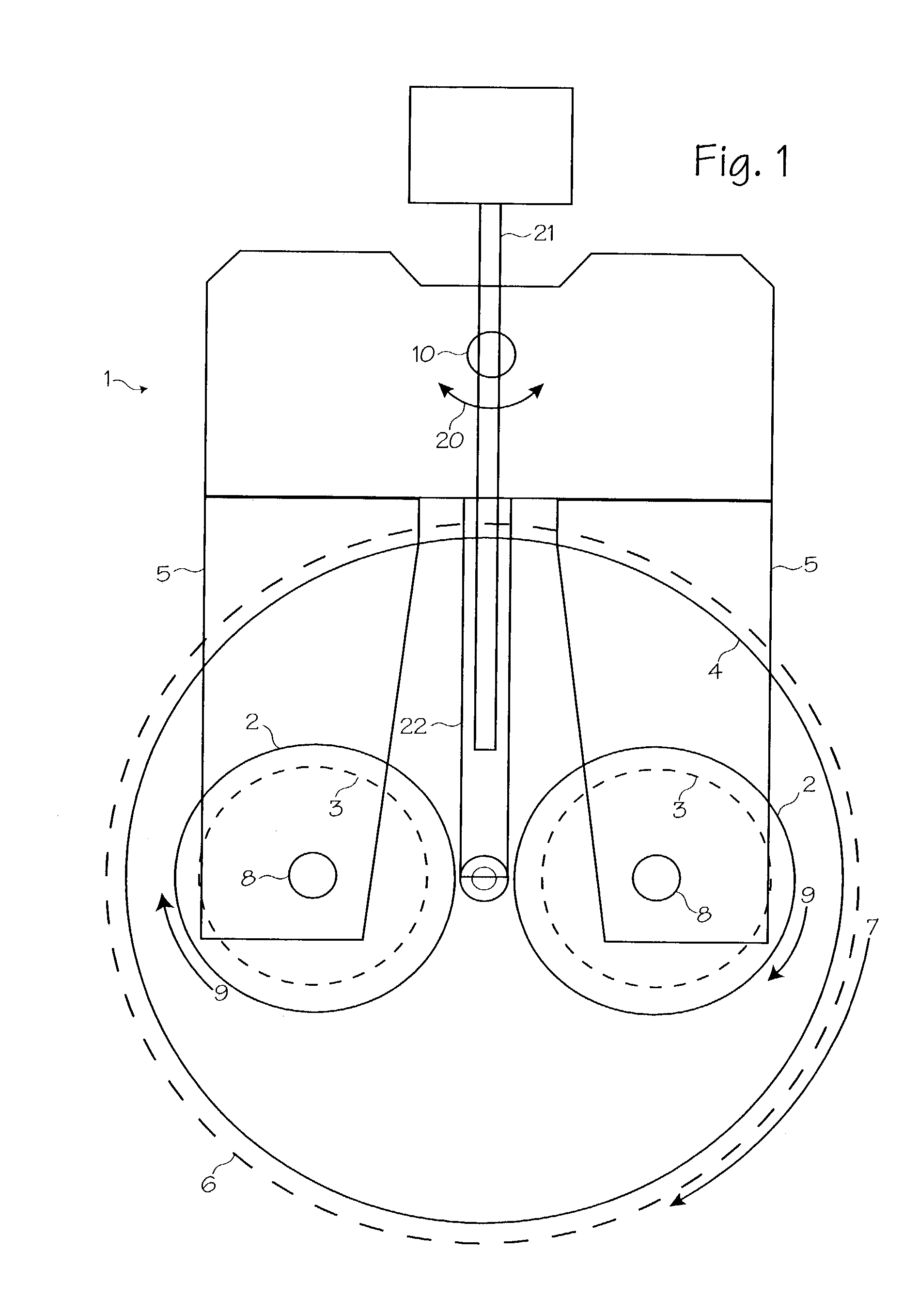
[0019]FIG. 1 shows a system 1 for performing chemical mechanical planarization. One or more polishing heads or wafer carriers 2 hold wafers 3 (shown in phantom to indicate their position underneath the wafer carrier) suspended over a polishing pad 4. The wafer carriers are suspended from translation arms 5. The polishing pad is disposed on a platen 6, which spins in the direction of arrow 7. The wafer carriers 2 rotate about their respective spindles 8 in the direction of arrows 9. The wafer carriers are also translated back and forth over the surface of the polishing pad by the translating spindle 10, which moves as indicated by arrow 20. The slurry used in the polishing process is injected onto the surface of the polishing pad through slurry injection tube 21, which is disposed on or through a suspension arm 22. (Other chemical mechanical planarization systems may use only one wafer carrier that holds one wafer, or may use several wafer carriers that hold several wafers. Other sys...


PUM


Abstract

A wafer carrier with a back pressure applicator system adapted to provide high resolution back pressure control. A plurality of millimeter scale distensible elements are disposed between the wafer carrier pressure plate and a process wafer, and selectively distended to provide excess backpressure to select small areas of a wafer known to exhibit resistance to removal vis-á-vis the surrounding wafer surface. Distensible elements may be in the form of expandable pneumatic chambers or electro-mechanical elements such as solenoids, shape memory elements, electrostatic plates, etc.

Description

FIELD OF THE INVENTIONS[0001]The inventions described below relate the field of wafer carriers used to hold wafers during chemical mechanical planarization.BACKGROUND OF THE INVENTIONS[0002]Integrated circuits, including computer chips, are manufactured by building up layers of circuits on the front side of silicon wafers. An extremely high degree of wafer flatness and layer flatness is required during the manufacturing process. Chemical mechanical planarization (CMP) is a process used during device manufacturing to flatten wafers and the layers built-up on wafers to the necessary degree of flatness.[0003]Chemical mechanical planarization is a process involving polishing of a wafer with a polishing pad combined with the chemical and physical action of a slurry pumped onto the pad. The wafer is held by a wafer carrier, with the backside of the wafer facing the wafer carrier and the front side of the wafer facing a polishing pad. The polishing pad is held on a platen, which is usually...

Claims


Application Information

Patent Timeline
Patent Type & Authority Patents(United States)
IPC IPC(8): B24B7/22B24B37/30B24B49/16
CPCB24B49/16B24B37/30
Inventor STRASBAUGH, ALAN
Owner REVASUM INC
Why Eureka
Try Eureka