
Method for fabricating a seal-integrated separator

a technology of integrated separator and seal, which is applied in the manufacture of cell components, sustainable manufacturing/processing, and final product production, etc., can solve the problems of unsatisfactory sealing performance, and achieve the effect of reducing the forming time and avoiding local pressure reduction

Inactive Publication Date: 2006-03-07
HONDA MOTOR CO LTD
View PDF22 Cites 33 Cited by
  • Summary
  • Abstract
  • Description
  • Claims
  • Application Information

AI Technical Summary

Benefits of technology

[0014]Tension in the protruding portion 2a may degrade the durability of the solid polymer electrolyte membrane 2, and could cause failure thereof in a short period, under repeated changes from hot to cold.
[0053]According to the above method, deformation of the separator body due to the injection pressure can be preferably prevented when the melted seal material flows through the through hole; thus, accuracy of the product can be improved.

Problems solved by technology

As shown in FIG. 19, for example, if the two seals 3a and 3b are disposed with a lateral offset with respect to each other as shown in the figure, the area of the solid polymer electrolyte membrane 2 sandwiched between the seals 3a and 3b (hereinafter referred to as “sealed area”) is reduced; consequently, the desired sealing performance will not be properly achieved.

Method used


Image

  • Method for fabricating a seal-integrated separator
  • Method for fabricating a seal-integrated separator
  • Method for fabricating a seal-integrated separator

Examples


Embodiment Construction

[0075]The preferred embodiments of the present invention will be explained with reference to the accompanying drawings.

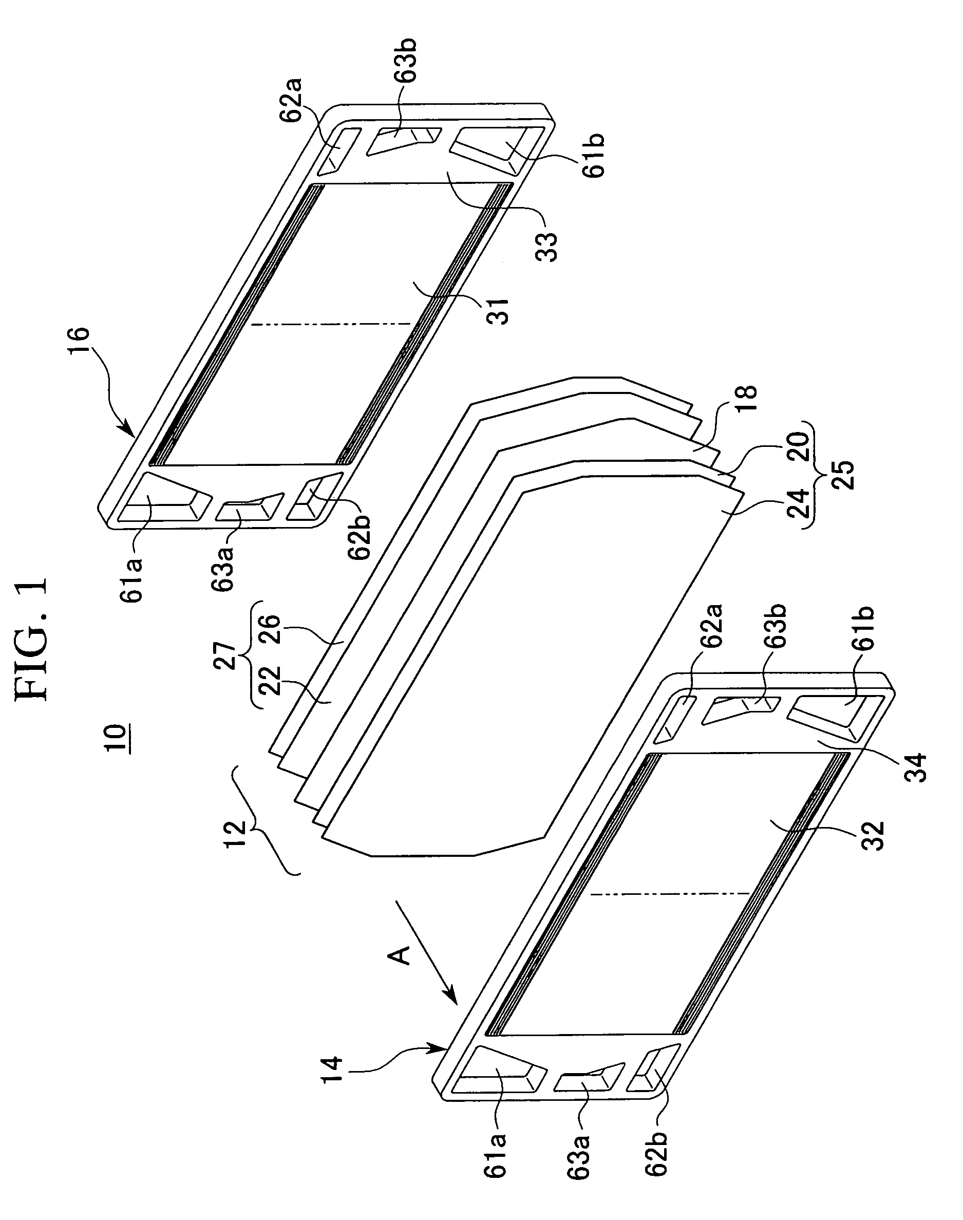
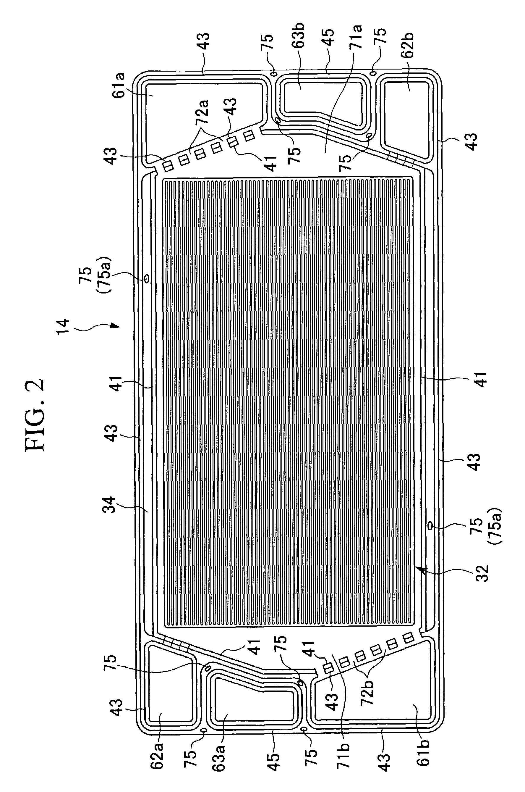
[0076]FIG. 1 is an exploded perspective view of a fuel cell comprising seal-integrated separators fabricated through a method according to the present invention, and FIG. 2 is an overhead view of one of the seal-integrated separators (a cathode side separator 14) shown in FIG. 1 viewed from the direction indicated by the arrow A.

[0077]Seals are not shown in FIG. 1.

[0078]A fuel cell unit 10 comprises a membrane electrode assembly 12 which is held between the cathode side separator 14 and an anode side separator 16.

[0079]A fuel cell stack for vehicles is fabricated by laminating and integrating several sets of the fuel cell unit 10 (e.g., four sets in FIG. 4) by means of fastening elements such as bolts and nuts.

[0080]The membrane electrode assembly 12 comprises: a solid polymer electrolyte membrane 18 made of, for example, perfluorosulphonate polymer; a cathode side ...


PUM


Abstract

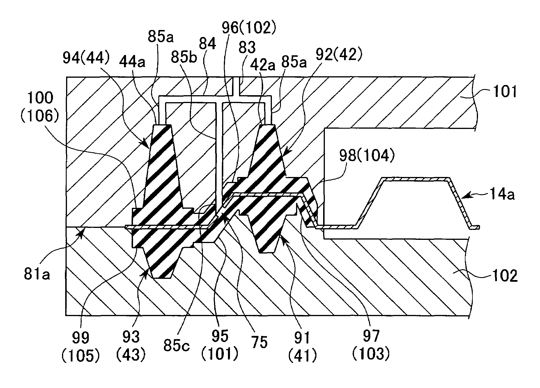
A method for fabricating a seal-integrated separator for a fuel cell is presented, with which seals can be accurately positioned and the assembling time for the fuel cell units may be greatly reduced. The method comprises the steps of: forming a through hole in the separator body; providing a first mold having grooves respectively positioned corresponding to the inner and outer seals disposed on one side of the separator body, a connecting cavity for forming a seal bridge at least partially connecting the inner and outer seals to each other at a position corresponding to the through hole, and at least one gate communicating with each of the grooves, and a second mold having grooves respectively positioned corresponding to the inner and outer seals disposed on the other side of the separator body, and a connecting cavity for forming a seal bridge at least partially connecting the inner and outer seals to each other at a position corresponding to the through hole; holding the separator body between the first mold and the second mold; and injecting melted seal material to form the seals into each of the grooves in the first mold by supplying the melted seal material into the gate and injecting a portion of the melted seal material into each of the grooves in the second mold via the through hole. Through this method, a seal-integrated separator having first to fourth seals which are integrated on both sides of the separator body is fabricated.

Description

BACKGROUND OF THE INVENTION[0001]1. Field of the Invention[0002]This invention relates to a method for fabricating a seal-integrated separator comprising a separator body for a fuel cell and a seal integrally formed on the separator body.[0003]2. Background Art[0004]Some fuel cell units comprise: a membrane electrode assembly consisting of a solid polymer electrolyte membrane sandwiched between an anode gas diffusion electrode and a cathode gas diffusion electrode; and a pair of separators holding the membrane electrode assembly therebetween.[0005]In a fuel cell of the above type, passages for a fuel gas, e.g., hydrogen, are formed on the anode side separator surface which faces the anode gas diffusion electrode, passages for an oxidizing gas, e.g., oxygen-containing air, are formed on the cathode side separator surface which faces the cathode gas diffusion electrode, and passages for a cooling medium are formed between two separators disposed adjacent to each other.[0006]When the f...

Claims


Application Information

Patent Timeline
IPC IPC(8): B29C45/14B29C33/42H01M8/02H01M8/10
CPCB29C45/14344H01M8/0228H01M8/0276H01M8/0254Y02E60/50H01M8/0282H01M8/0273Y02P70/50H01M8/0271
Inventor INOUE, MASAJIROSUENAGA, TOSHIHIKOKIMURA, NOBUAKIANDOU, KEISUKE
Owner HONDA MOTOR CO LTD
Learn More