Image pickup apparatus

a technology of image pickup and apparatus, which is applied in the direction of instruments, television systems, optical elements, etc., can solve the problems of apparatus does not lend itself to mass production, and image pickup apparatuses are required to achieve individual adjustment of focusing, so as to accurately define the relative position between the optical system and the image pickup element. , the effect of small assembly errors

Inactive Publication Date: 2006-03-07
MITSUBISHI ELECTRIC CORP
View PDF19 Cites 27 Cited by
  • Summary
  • Abstract
  • Description
  • Claims
  • Application Information

AI Technical Summary

Benefits of technology

[0024]An object of the invention is to provide an image pickup apparatus that requires only a smaller number of structural components and no adjustment operation of focus, provides smaller assembly errors, and lends itself to mass production.
[0025]An image pickup apparatus includes an image pickup element, an optical system or lens, and a supporting member. The image pickup element has a first surface and a second surface opposite to the first surface. The image pickup element has an image region formed in the first surface. The optical system causes image light from a subject to form an image on the image region. The supporting member engages the image pickup element and the optical system. The supporting member has a first abutment portion that directly abuts the optical system and a second abutment portion that directly abuts the image pickup element, thereby accurately defining the relative position between the optical system and the image pickup element.

Problems solved by technology

Moreover, the image pickup apparatus suffers from the problem that individual adjustment of focusing is required after the barrel 21 has been assembled to the lens holder 23.
Thus, the apparatus does not lend itself to mass production.
FIG. 9 illustrates factors that cause assembly errors, which in turn affect the focusing performance of an image pickup apparatus of the aforementioned construction.
An error ΔA of the back focus is an error that results from an error of a radius of curvature of the lens 33.
The conventional image pickup apparatus of the aforementioned configurations require individual focus adjustment during manufacture of image pickup apparatus, being inefficient in mass production.
However, forming an optical system by a two-color molding suffers from a serious technical difficulty because the radius of curvature of the lens 40 requires to be very accurately controlled.
Thus, molding the optical system from materials of different colors does not lend itself to mass production.
Further, the construction where the lens and lens-mounting member are formed in one-piece construction does not lend itself to mass production.
The construction where the optical holder abuts a part of the image pickup element suffers from the problem that there are limitations on the position at which the substrate is mounted.
The aforementioned conventional apparatus suffer from the inherent problem that the circuit board is disposed under the image pickup element and therefore the thickness of the circuit board adds to the overall size of the image pickup apparatus.

Method used


Image

  • Image pickup apparatus
  • Image pickup apparatus
  • Image pickup apparatus

Examples


embodiment

{Construction}

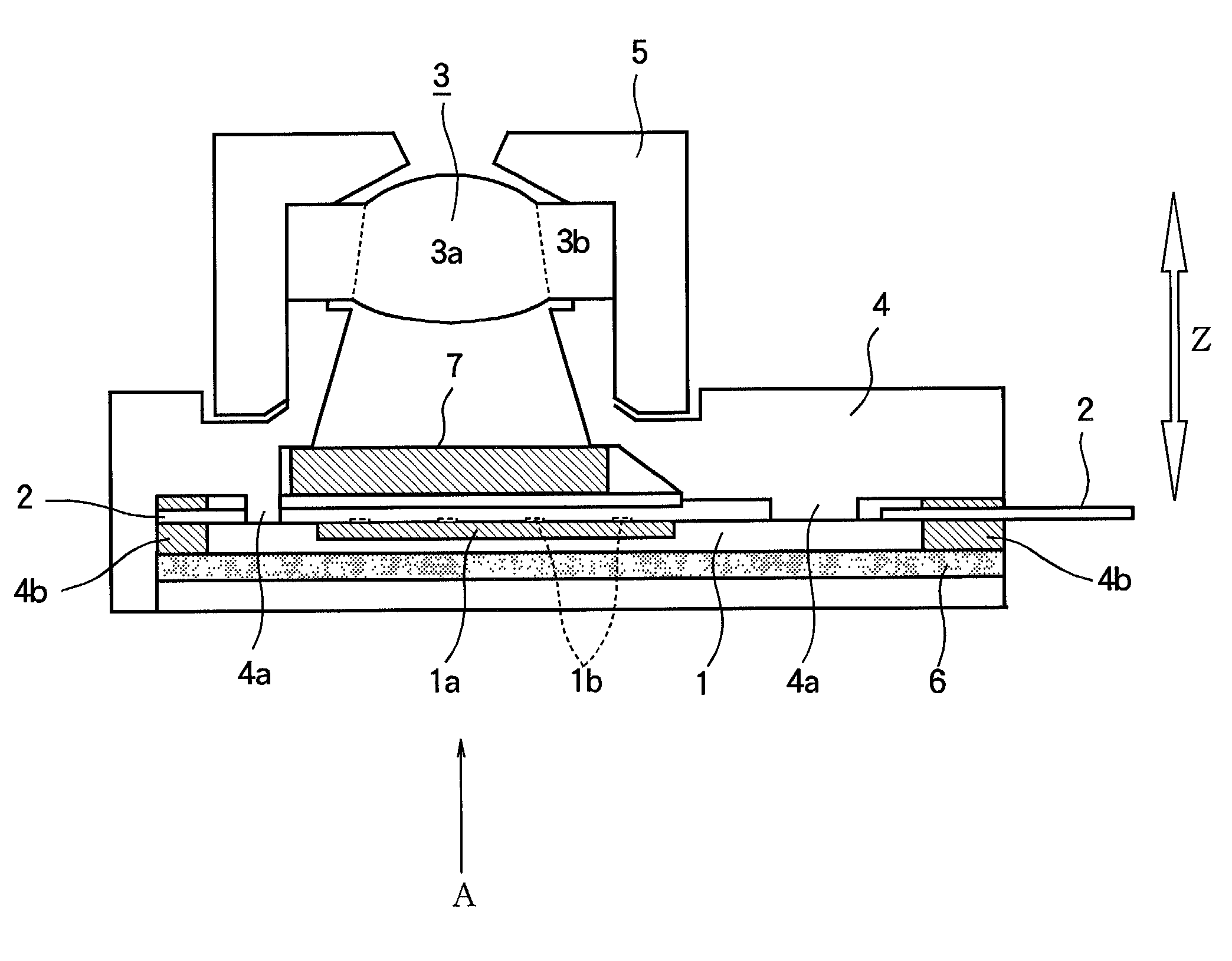
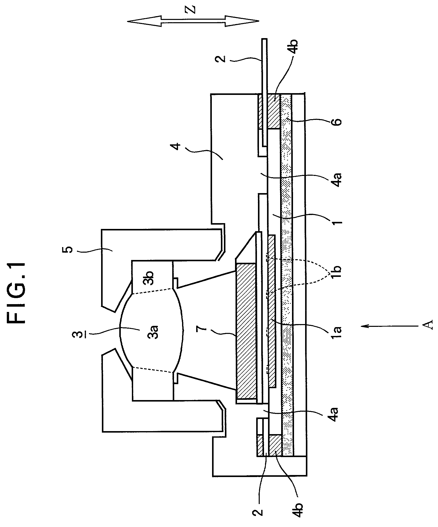
[0050]FIG. 1 illustrates a configuration of an image pickup apparatus according to the present invention.

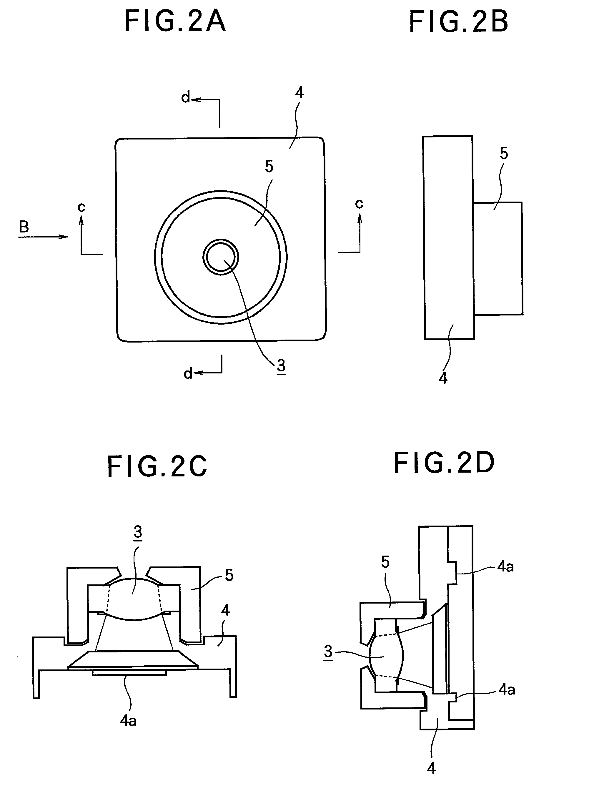
[0051]FIGS. 2A and 2B illustrate an outside shape of an optical system, holder, and barrel of the image pickup of FIG. 1.

[0052]FIGS. 2C and 2D illustrate an inside shape of the optical system, holder, and barrel.

[0053]Referring to FIG. 1, the image pickup element 1 takes the form of a bare chip (i.e., just diced from a semiconductor wafer and not packaged). The image pickup element 1 has an image region 1 and electrodes 1b. The image region 1a converts an image of a subject, focused thereon by the optical system 3, into an electrical signal. The electrical signal is directed from the image region 1a to external circuits through the electrodes 1b.

[0054]FIG. 3A is an enlarged side view of the image pickup element bonded to a substrate 2.

[0055]FIG. 3B is a top view of the image pickup element 1 bonded to the substrate 2 when the image pickup element 1 is viewed in a d...


PUM


Abstract

An image pickup apparatus captures an image from a subject without a focus-adjusting mechanism. An image pickup element has opposed first and second surfaces and an image region formed in the first surface. An optical system causes the image light from the subject to form an image on the image region. A supporting member has a first abutment portion that engages the optical system with nothing sandwiched therebetween, and a second abutment portion that engages the image pickup element with nothing sandwiched therebetween, thereby accurately positioning the optical system relative to the image pickup element. The second abutment portion abuts an area on the first surface except for the image region. A circuit board is fixed to the supporting member and electrically connected to the image pickup element. The circuit board has an opening formed therein such that the image region is exposed through the opening.

Description

BACKGROUND OF THE INVENTION[0001]1. Field of the Invention[0002]The present invention relates to an image pickup apparatus that does not require a focus-adjusting mechanism for an optical system.[0003]2. Description of the Related Art[0004]FIG. 7 illustrates a conventional compact image pickup apparatus.[0005]A barrel 21 has an outer threaded cylindrical surface 21a and a lens holder 23 has an inner threaded cylindrical surface 23a. The barrel 21 is threaded into the lens holder 23 such that the outer threaded cylindrical surface 21a fittingly engages the inner threaded cylindrical surface 23a. The barrel 21 holds a lens 20 mounted therein and has a rear aperture 22 disposed behind the lens 20. The lens holder 23 holds a substrate 26 at a bottom thereof. An image pickup element 25 is mounted on the substrate 26 and has an image region 25a fabricate on a surface thereof. The image region 25a is electrically connected via bonding wires 25b to leads 25c mounted on the substrate 26.[000...

Claims


Application Information

Patent Timeline
Patent Type & Authority Patents(United States)
IPC IPC(8): H04N5/225G02B7/02H01L31/0203H01L31/0232H04N5/335
CPCG02B7/02H01L27/14618H01L27/14625H04N5/2254H01L31/0232H04N5/2253H01L31/0203H01L2224/48091H01L2224/73265H01L31/02325H04N23/54H04N23/55H01L2924/00014
Inventor KUNO, TETSUYASUGIURA, HIROAKIMIYAKE, HIROYUKI
Owner MITSUBISHI ELECTRIC CORP
Why Eureka
Try Eureka