Method for investigating a sample

a sample and fluorescence technology, applied in the field of laser scanning microscopy, fluorescence correlation spectroscopy, nearfield scanning microscopy, can solve the problems of difficult separation of emission signals with dbs, troublesome superposition of background signals, and increased difficulty or sometimes even impossible investigation, so as to reduce the sensitivity of detection, increase the noise of detectors, and increase the effect of amplification

Inactive Publication Date: 2006-03-07
CARL ZEISS MICROSCOPY GMBH
View PDF7 Cites 95 Cited by
  • Summary
  • Abstract
  • Description
  • Claims
  • Application Information

AI Technical Summary

Benefits of technology

[0027]The invention has as its primary object novel methods for flexible and freely programmable detection by which dyes which differ from each other only slightly with respect to their absorption characteristics and emission characteristics can be measured and displayed separately in an image-generating microscope system. With the method according to the invention, crosstalk between the individual dyes is reliably detected and eliminated by data processing.
[0031]The quantity of dye signatures that may be used simultaneously, i.e., the quantity of characteristics, for example, of cells that can be investigated simultaneously, can be increased by means of the method according to the invention. When the spectral signatures of the individual dyes overlap extensively, the wavelength range must be limited, according to the prior art, for separate detection of the fluorescence signals of individual dyes. This reduces the sensitivity of detection, i.e., increases the noise of the detectors, because greater amplification is used. This is avoided by the method according to the invention. Further, nonspecific fluorescence signals, autofluorescence and fluorescence of the measuring device can be separated out.

Problems solved by technology

The emission spectra of different dyes shown in FIG. 3b can also overlap extensively, so that a separation of the emission signals with DBS is difficult.
Superimposition of background signals is a troublesome, unwanted effect in multifluorescence recordings.
These background signals can be reflections of individual lasers on the specimen or broadband autofluorcscence signals of specimen components which are superimposed on the spectral signatures of the fluorescence-labeled specimen locations to be investigated and therefore render this investigation more difficult or sometimes even impossible.

Method used


Image

  • Method for investigating a sample
  • Method for investigating a sample
  • Method for investigating a sample

Examples


Embodiment Construction

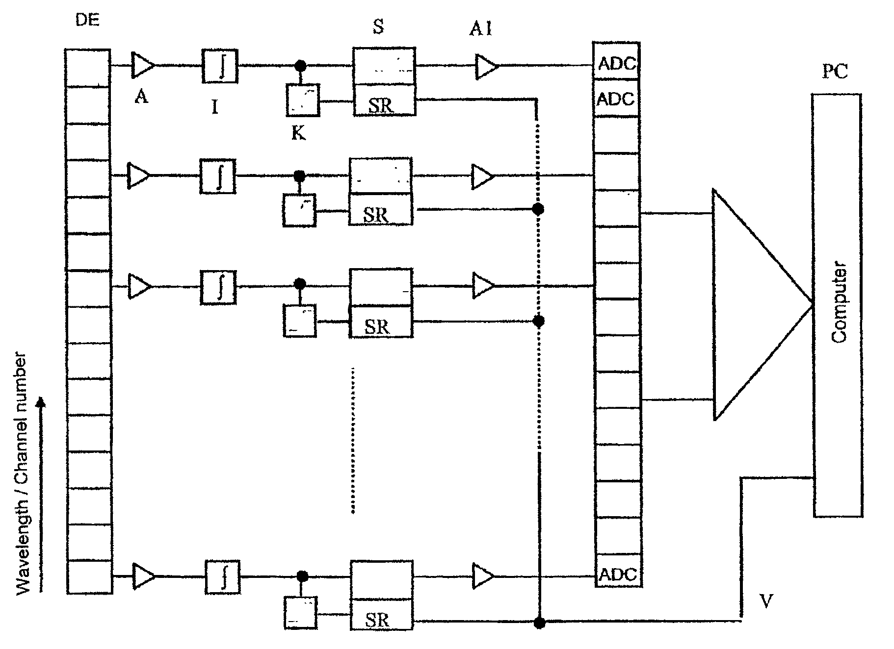
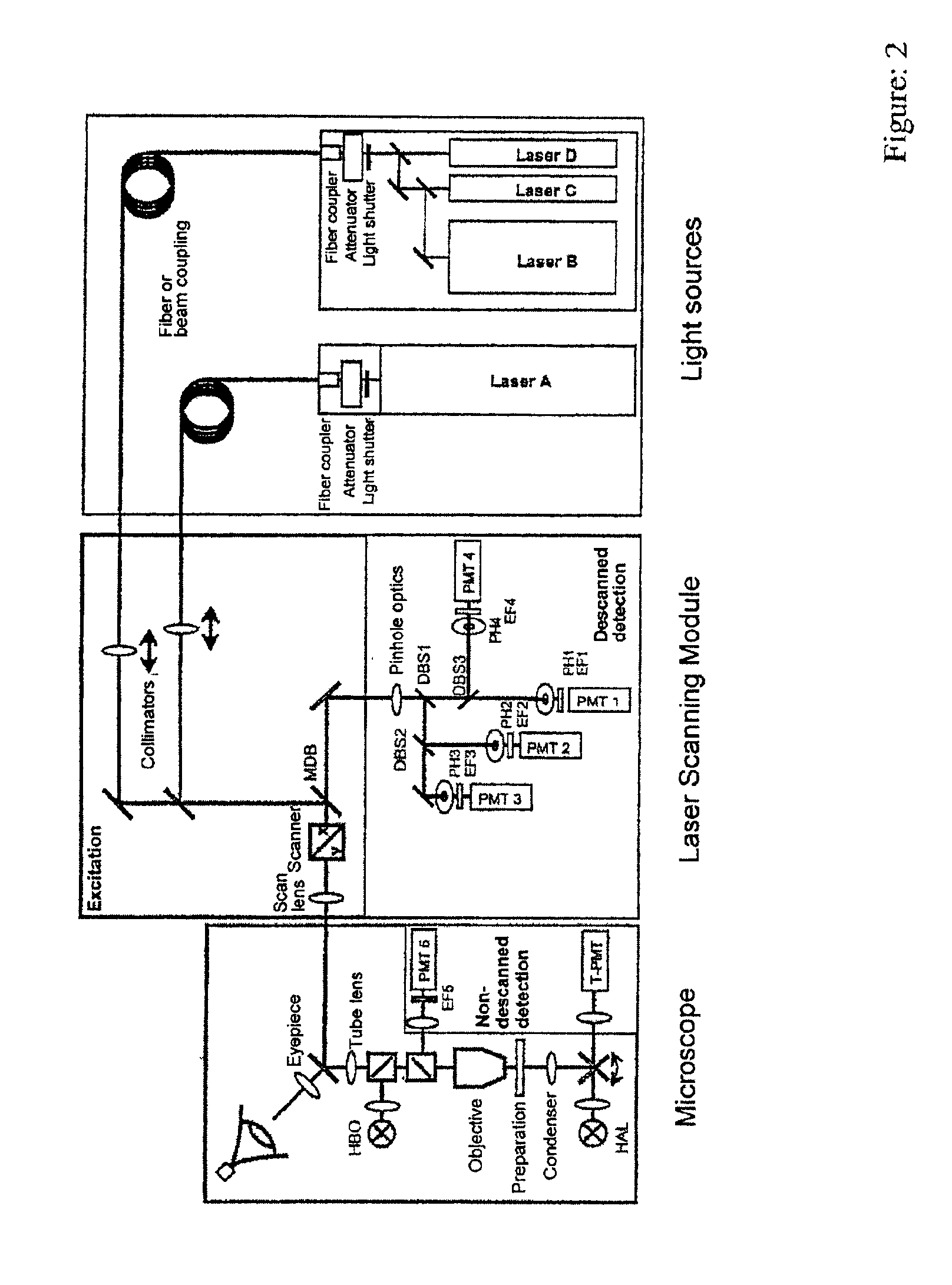
[0060]The background of the method according to the invention is a spectrally split detection of fluorescence. For this purpose, the emission light is split from the excitation light in the scan module or in the microscope (with multiphoton absorption) by means of an element for separating the excitation radiation from the detected radiation, such as the main color splitter (MDB) or an AOTF according to 7346DE or 7323DE. With transmitted-light arrangements, this type of element can also be entirely omitted. A block diagram of the detector unit to be described is shown in FIG. 5. With confocal detection, the light L from the specimen is focused through a diaphragm (pinhole) PH by means of imaging optics PO, so that fluorescence occurring outside of the focus is suppressed. In nondescanned detection, the diaphragm is omitted. The light is now divided into its spectral components by an angle-dispersive element DI. The angle-dispersive elements can be prisms, gratings and, e.g., acousto...


PUM

PropertyMeasurementUnit
wavelengthaaaaaaaaaa
wavelength rangeaaaaaaaaaa

Abstract

A method for investigating specimens, wherein a spectral splitting of the radiation coming from the specimen is carried out for specimen points or point distributions, for the operation of a laser scanning microscope or a fluorescence screening arrangement or a flow cylinder comprising the steps of generating a λ-stack so that the spectral distribution is measured by individual detection channels and storing the signals so as to be correlated to the detection signals with at least one of the spatial coordinates x, y and z and / or so as to be correlated to the measurement time t.

Description

CROSS-REFERENCE TO RELATED APPLICATIONS[0001]This application claims priority of German Application No. 101 51 217.1, filed Oct. 16, 2001, the complete disclosure of which is hereby incorporated by reference.BACKGROUND OF THE INVENTION[0002]a) Field of the Invention[0003]The invention is directed to a method in fluorescence microscopy, particularly laser scanning microscopy, fluorescence correlation spectroscopy, and nearfield scanning microscopy, for the examination of predominantly biological specimens, preparations and associated components. This includes methods for screening active ingredients based on fluorescence detection (high throughput screening). The transition from the detection of a few broad-spectrum dye bands to the simultaneous acquisition of whole spectra opens up new possibilities for the identification, separation and correlation of mostly analytic or functional specimen characteristics to spatial partial structures or dynamic processes. Therefore, simultaneous i...

Claims


Application Information

Patent Timeline
Patent Type & Authority Patents(United States)
IPC IPC(8): G01N21/64G01J3/28G01J3/44G02B21/00
CPCG01J3/2803G01J3/4406G01N21/6408G01N21/6428G01N21/6458G02B21/0084G02B21/0064G02B21/0076G02B21/008G01N2021/6423G01N2021/6441G01N2021/6421
Inventor WOLLESCHENSKY, RALFZIMMERMANN, BERNHARDTILLE, SESBASTIAN
Owner CARL ZEISS MICROSCOPY GMBH
Why Eureka
Try Eureka