System and method for multi-channel mitigation of PMD/PDL/PDG

a multi-channel mitigation and multi-channel technology, applied in multiplex communication, polarising elements, instruments, etc., can solve the problems of reducing the tolerance of the system to pmd, and affecting the performance of the system, so as to eliminate the pmd-induced system outage in the nrz, the effect of effective correction of dominating errors occurring during transmission

Inactive Publication Date: 2006-03-07
LUCENT TECH INC +1
View PDF2 Cites 13 Cited by
  • Summary
  • Abstract
  • Description
  • Claims
  • Application Information

AI Technical Summary

Benefits of technology

[0010]The present invention provides a system and method for multi-channel PMD / PDL / PDG mitigation and outage prevention in which FEC is used in conjunction with sub-burst-error-correction-period (s-BECP) PMD vector scrambling (PMDS) using distributed, fast polarization scramblers (D-FPSs). BECP is in units of time, which equals burst error correction length (BECL) multiplied by the bit period. For ITU standard G.709, BECL=1024 bits. Thus, in a G.709 standardized 10.7-Gb / s system, the BECP is approximately 1024×100 ps≈0.1 μs. The link PMD is preferably changed to at least two random states within each BECP simultaneously for all wavelength channels. By limiting PMD induced “outages” to last for a period that is shorter than the correcting period, FEC can effectively correct the dominating errors occurring during transmission. The present invention provides significant improvement in system tolerance to PMD and can essentially eliminate PMD induced system outages in NRZ and RZ transmissions.
[0011]According to one embodiment, the present invention is a system for mitigating the penalties from PMD, PDL and PDG. The system comprises at least one polarization scrambler adopted to vary the polarization state of an optical signal to effectively vary the polarization mode dispersion experienced by the signal at least once during each BECP of the FEC used in the system.

Problems solved by technology

As a result, the waveform of optical signals may be significantly distorted, resulting in more frequent errors at the receiver.
PDL and PDG cause signals to have different amplitudes at the receiver, which makes the optimal decision threshold different for different bits (depending on their polarization), and thus degrades the receiver performance when the receiver decision threshold can only be fixed to a certain level for all the bits.
PDL may also cause varying optical signal-to-noise-ratio (OSNR) for bits with different polarization, and further degrade the system performance.
PDL or PDG induced OSNR degradation cannot be compensated for since the process of adding random amplified spontaneous emission (ASE) noise cannot be undone.
However, due to the stochastic nature of PMD and its wavelength dependence, PMDC is normally required to be implemented for each wavelength channel individually, and is thus generally not cost-effective.
However, such systems sacrifice system capacity due to the use of extra channels for PMD protection.
However, such a mitigation scheme may cause degradation of other channels.
Another scheme for a multi-channel shared PMDC has been proposed in which the most degraded channel is switched, by optical or electrical means, to a path connected to the shared PMDC; however, the speed of PMDC is limited (by the speed of the optical or electrical switching).
It has been determined, however, that FEC cannot extend the tolerable PMD for a fixed PMD penalty at a given average bit-error-rate (BER), even though the additional margin provided by FEC can be used to increase the PMD tolerance.
However, there is no known practical method to provide the deep interleaving needed to avoid a PMD outage which may last minutes or longer in practical systems.

Method used


Image

  • System and method for multi-channel mitigation of PMD/PDL/PDG
  • System and method for multi-channel mitigation of PMD/PDL/PDG
  • System and method for multi-channel mitigation of PMD/PDL/PDG

Examples


Embodiment Construction

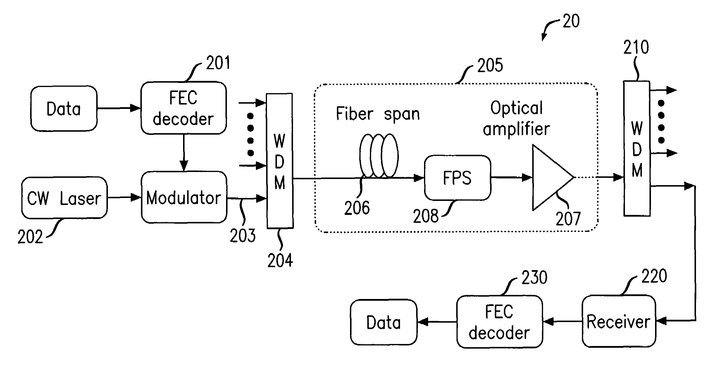
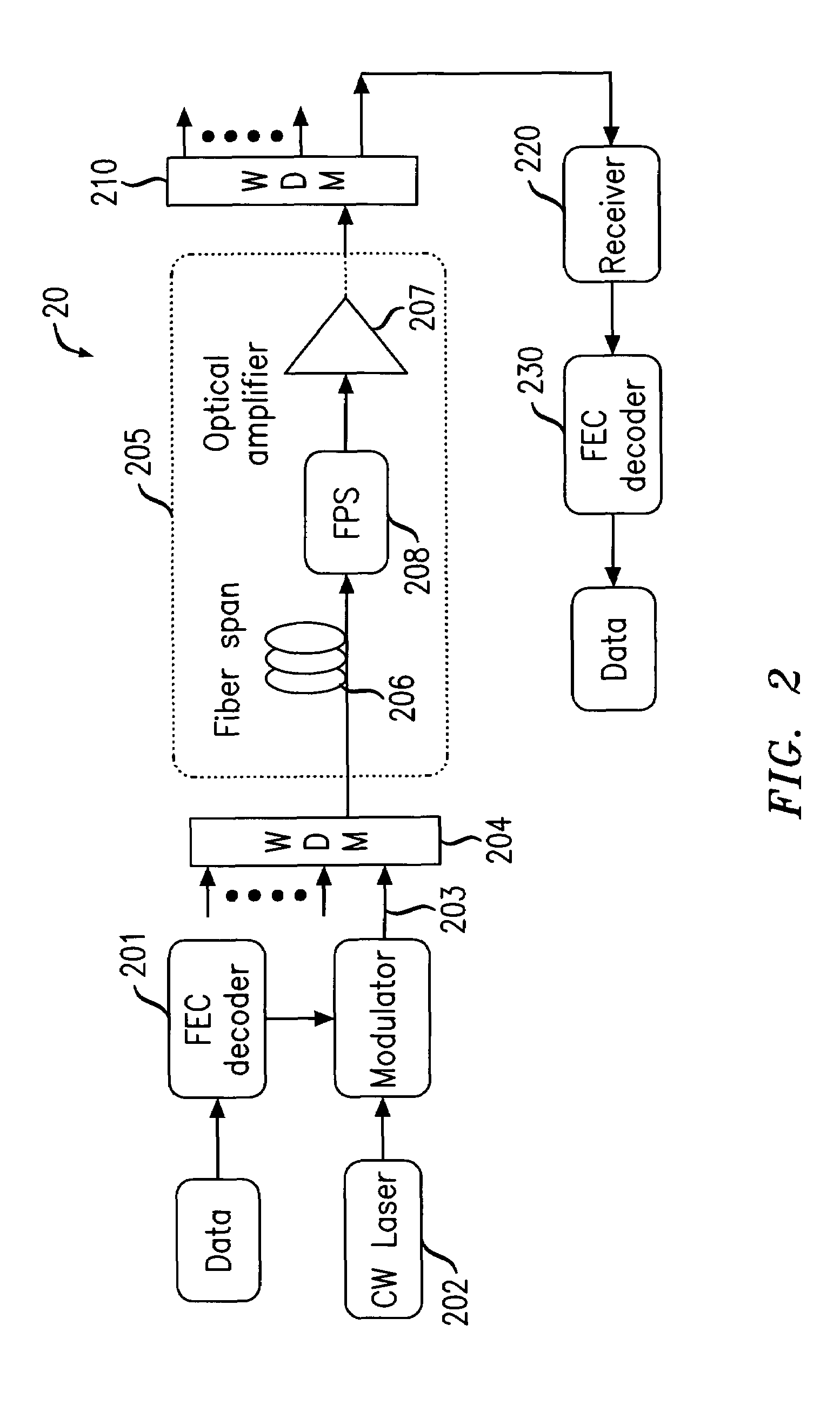
[0021]One aspect of the present invention proposes the use of FEC in conjunction with fast polarization scrambling to change the polarization of a signal between at least two states during each FEC burst-error-correcting period (BECP). By changing the link PMD at least once during each BECP the PMD induced “outages” are effectively limited to last for a period that is shorter than the correcting period, thus the FEC can effectively correct the dominating errors that occurred during the outages, and thereby improve system tolerance to PMD and prevent system outage, simultaneously for all wavelength channels

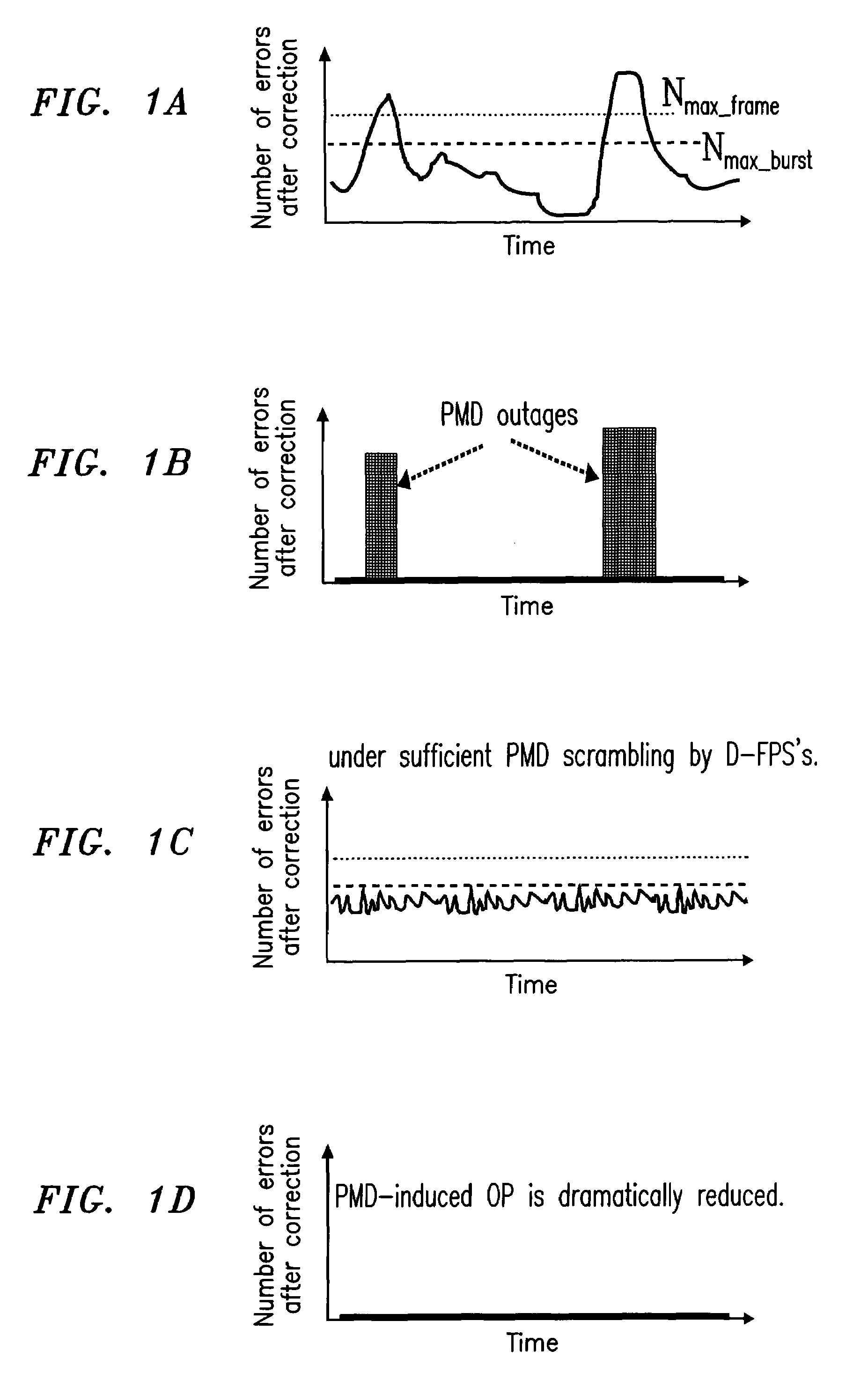
[0022]FIGS. 1A–D illustrate a working principle of present invention. FIGS. 1A–B show the case without D-FPSs. As shown in FIGS. 1A–B, PMD occasionally causes severe signal waveform distortion, which results in consecutive or very frequent errors. Such PMD-induced distortion can last from milliseconds up to minutes.

[0023]For any given FEC code, there is a maximum number of correcta...


PUM


Abstract

A system and method for multi-channel PMD / PDL / PDG mitigation, the system including polarization scramblers adapted to vary the state of polarization of an optical signal propagated through the system to effectively vary the polarization mode dispersion experienced by the signal during each burst-error-correcting-period of the forward error correction used in the system.

Description

CROSS-REFERENCE TO RELATED APPLICATION[0001]This is a continuation-in-part application of U.S. patent application Ser. No. 10 / 631,654 entitled “System And Method For Multi-Channel Mitigation of PMD / PDL / PDG” filed on Jul. 31, 2003 now abandoned which is incorporated herein by reference.FIELD OF THE INVENTION[0002]The present invention relates to optical communications, and more specifically to a system and method for mitigating the penalties resulting from polarization-mode-dispersion (PMD), polarization-dependent loss (PDL), and polarization-dependent gain (PDG) in optical communication systems.BACKGROUND OF THE INVENTION[0003]Polarization-mode-dispersion (PMD) is a common phenomenon that occurs when light waves travel in optical media such as optical fiber and optical amplifiers. PMD occurs in an optical fiber as a result of small birefringence induced by deviations of the fiber's core from a perfectly cylindrical shape, asymmetric stresses or strains, and / or random external forces...

Claims


Application Information

Patent Timeline
Patent Type & Authority Patents(United States)
IPC IPC(8): G02B6/00H04B10/02G02B6/27H04B10/18H04J14/00H04J14/02
CPCH04B10/2569H04B2210/256
Inventor VAN WIJNGAARDEN, ADRIAAN J. DE LINDLIU, XIANGXIE, CHONGJIN
Owner LUCENT TECH INC
Why Eureka
Try Eureka