Image forming apparatus, drum unit, image forming module, and method of insertion and removal of a damper into and from an image carrier drum

Inactive Publication Date: 2006-03-07
RICOH KK
View PDF38 Cites 14 Cited by
  • Summary
  • Abstract
  • Description
  • Claims
  • Application Information

AI Technical Summary

Benefits of technology

[0029]According to another aspect of this invention, an image forming apparatus includes a toner image forming unit that forms a toner image on an image carrier drum using a toner having an outflow start temperature less than or equal to 102° C. measured by flo

Problems solved by technology

However, in the structure, discharge products like ozone and nitrogen oxide are generated during discharging which may result in deterioration of environment or deterioration of charging characteristics on the photoreceptor.
The deposits that have undergone reverse transition hinder the injection of charge and may deteriorate the charging characteristics.
Furthermore, when a charging member is left without being used in a charging process for hours, a portion of the charging member that is in contact with the photoreceptor, changes shape due to permanent deformation.
As a result, when the charging process is carried out again, there is no uniform contact of the charging member with the surface of the photoreceptor, which may result in charging unevenness.
Depending on a setting of the bias characteristics that is carried out in the charging unit and the developing unit, noise is caused by applying ac voltage during shifting of the photoreceptor.
Furthermore, due to a cleaning blade of the cleaning unit that is in contact with the photoreceptor, the vibrations are generated in the thin-walled cylinder due to repetition of deformation and restoration of shape of the cleaning blade when the cleaning blade scrapes the photoreceptor, and resonance in the photoreceptor produces noise.
The image carrier drum vibrates due to an external force that imparts vibrations, thereby resulting in generation of noise from the image carrier drum.
The vibrations are transmitted to the image carrier drum to make the image carrier drum vibrate, and to thereby generate noise.
A user may feel unpleasant because of noise.
However, a case of using the toner having a low melting point tend to generate noise easily as compared to a case of using a toner having a high melting point.
Therefore, it is found that the conventional damper is unable to reduce the noise sufficiently.
It is n

Method used


Image

  • Image forming apparatus, drum unit, image forming module, and method of insertion and removal of a damper into and from an image carrier drum
  • Image forming apparatus, drum unit, image forming module, and method of insertion and removal of a damper into and from an image carrier drum
  • Image forming apparatus, drum unit, image forming module, and method of insertion and removal of a damper into and from an image carrier drum

Examples


first embodiment

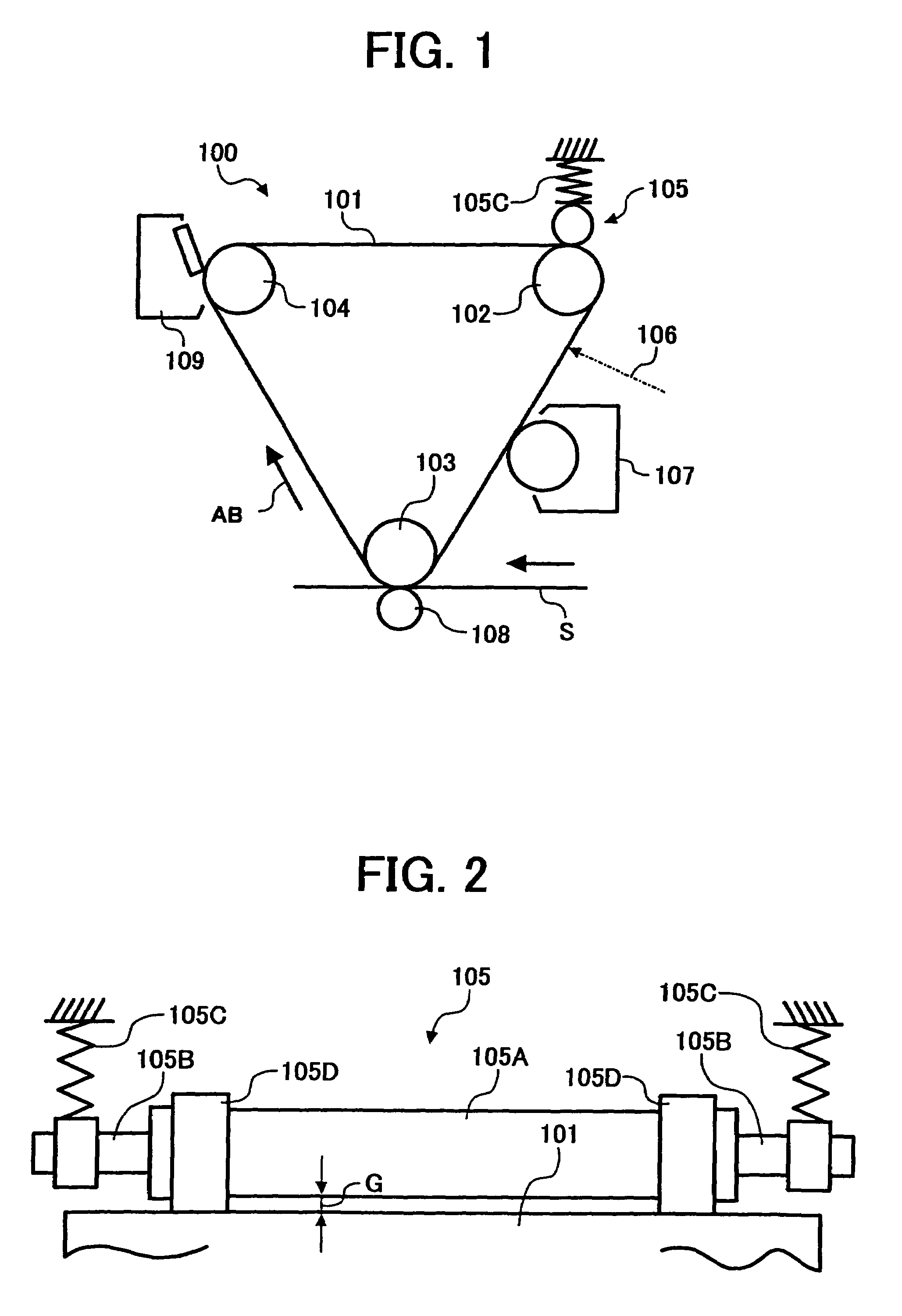
[0087]FIG. 1 is a schematic diagram of an image forming unit of an image forming apparatus 100 according to a In the image forming apparatus 100, a photoreceptor that functions as a latent image carrier, is formed by a belt (hereinafter, “photoreceptor belt 101”). The photoreceptor belt 101 is wound around among a plurality of rollers 102 to 104 and can move in a direction indicated by an arrow AB. A charging unit 105, a writing unit 106 (in FIG. 1, only optical path is shown), a developing unit 107, a transferring unit 108, and a cleaning unit 109 are disposed around the photoreceptor belt 101 along the direction of movement of the belt to carry out image forming processing.

[0088]The rollers 102 to 104 are arranged such that the photoreceptor belt 101 forms a triangle turned upside down as shown in FIG. 1 and a vertex of the triangle is a transferring position.

[0089]The charging unit 105 is one of the units which sets bias characteristics in the photoreceptor belt 101. As shown in...

second embodiment

[0184]this invention will be explained below.

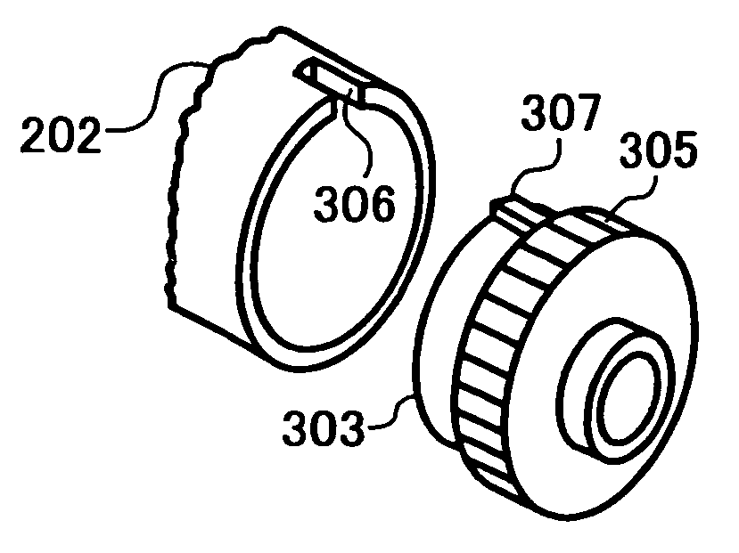
[0185]FIG. 15 is a cross section of a schematic structure of an image forming apparatus that uses an image carrier drum in the form of a hollow cylinder according to the second embodiment. An image carrier drum 202 in the figure is a photoreceptor drum with a photosensitive layer provided on an outer peripheral surface of a circular cylindrical tube made of a conductive metal like aluminum. In an example shown in FIG. 15, an image forming module 218 is structured by assembling the image carrier drum 202 integrally with an image forming unit that forms a toner image as explained later. The image carrier drum 202 is rotatably supported by a case 219 of the image forming module 218, and is driven by a drive motor (not shown) in the clockwise direction in FIG. 15. At this time, a charging roller 220 as an example of a charging unit rotatably supported by the case 219 is rotated, and a charging voltage is applied to the charging roller 220. Th...

third embodiment

[0226]this invention will be explained below.

[0227]FIG. 21 is a cross section of an image forming unit of an image forming apparatus provided with an image carrier drum according to the third embodiment. An image carrier drum 202 in the figure is a photoreceptor drum which includes a photosensitive layer provided on an outer peripheral surface of a circular cylindrical tube made of a conductive metal like aluminum. The image carrier drum 202 is supported by a shaft 301 that extends through inside the image carrier drum 202 as explained later. Both ends of the shaft 301 along its length are supported by a case 219 of an image forming module 218. The image carrier drum 202 supported by the shaft 301 is rotated by a drive motor (not shown) in a clockwise direction as shown in FIG. 21. During rotation of the image carrier drum 202, a charging unit formed with a charging roller 220 rotatably supported by the case 219 rotates while being in contact with the outer peripheral surface of the...


PUM

PropertyMeasurementUnit
Elasticityaaaaaaaaaa
Dissipation factoraaaaaaaaaa

Abstract

An image forming apparatus includes a photoreceptor belt formed by either a belt or a thin-walled cylinder. A charging unit that sets bias characteristics of the photoreceptor belt has an arrangement to approach towards the photoreceptor belt. A damper is provided on a side of the photoreceptor belt opposite to the side facing the charging unit. The damper absorbs vibrations in the photoreceptor belt through a supporting plate.

Description

BACKGROUND OF THE INVENTION[0001]1) Field of the Invention[0002]The present invention relates to a technology for preventing noise caused by vibrational resonance produced in a latent image carrier due to a thin-walled structure of an image forming apparatus.[0003]2) Description of the Related Art[0004]In image forming apparatuses like a copying machine, a facsimile, a printer, and a printing machine, steps of charging, writing, developing, and transferring are carried out for a photoreceptor as a latent image carrier. In the step of transferring, a toner image that is transferred on a recording medium like a recording paper is fixed to give a copy or a printout.[0005]A structure that employs a non-contact charging method with aerial discharge using a corona charger is used for charging of the photoreceptor. However, in the structure, discharge products like ozone and nitrogen oxide are generated during discharging which may result in deterioration of environment or deterioration of...

Claims


Application Information

Patent Timeline
IPC IPC(8): G03G15/00
CPCG03G15/751G03G15/757Y10T29/49002Y10T464/50F16F15/10
Inventor FUJISHIRO, TAKATSUGUSUDA, TAKEOZEMBA, HIDEKIMURAYAMA, HISAO
Owner RICOH KK
Why Eureka
Try Eureka