Induction logging system and method featuring multi-frequency skin effect correction

a multi-frequency, skin effect correction technology, applied in the field of electromagnetically induction well logging instruments, can solve the problems of severe non-linearity of measured values, severe non-linearity, and traditional skin effect correction methods only boost the apparent conductivity, so as to save cost and effort in developing an induction tool

Active Publication Date: 2006-03-07
HALLIBURTON ENERGY SERVICES INC
View PDF6 Cites 7 Cited by
  • Summary
  • Abstract
  • Description
  • Claims
  • Application Information

AI Technical Summary

Benefits of technology

[0009]The invention overcomes the above-identified problems as well as other shortcomings and deficiencies of existing technologies by providing for correction of skin effect error in a conductivity measurement and in the geometric factors of the induction measurements in induction logging. The present invention obtains its measurements with a limited number (e.g., two or three) of measurements using different frequencies. The skin effect correction method, according to the present invention, takes the signal measurements and corrects for the skin effect of the apparent conductivity value and geometric factors, while at the same time being adequate for processing of data from modern array-type induction logging tools. The method, according to the present invention, provides a more efficient way to investigate formation conductivity. In addition, the present invention provides an adaptive way to control possible noise during measurement of the formation. Only the in-phase component of the measurement signal is necessary, however, the invention may be used with any type of complex signal waveform.
[0010]The present invention provides a reliable way to correct induction logs for the skin effect in order to apply advanced processing schemes to the logs, such as software focusing. Since only the in-phase component of a signal is required during measurement, the present invention does not need quadrature signal (X-signal) measurements, thus saving cost and effort in developing an induction tool.

Problems solved by technology

Second, the skin effect makes the response functions or geometric factors different from the ones derived under the Doll limit, thus causing severe non-linearity of the measured values.
Induction logging measurements are affected by skin effect in the aspects of apparent conductivity value and in the aspect of response functions or geometric factors as well, causing severe non-linearity.
Traditional skin effect correction methods only boost the apparent conductivity and are no longer suited for modern induction tools, such as array induction tools, which rely on linear numerical processing to obtain desired induction logs.
However, the quadrature signal component is prone to various noise, error, instability, etc., from the direct coupling through the geological formation.
A metal mandrel blocks the induction signal all through its cross section, thus for adequate signal level, the induction tool must have a large diameter, making it almost impossible to design a slim-hole array induction tool.
However, the measurement of the quadrature signal component often suffers from relatively small signal levels (when the formation is resistive), sonde error instability, severe temperature effects and distortion from magnetic materials in the drilling fluid.
The aforementioned drawbacks of measuring the quadrature signal component eventually limit the skin effect correction.
But, it leaves the radial geometric factor uncorrected.
To apply the method of Beard '057, a set of in-phase measurements must be made at multiple frequencies to form a simple spectrum with respect to frequency, which increases the cost of the induction logging.

Method used


Image

  • Induction logging system and method featuring multi-frequency skin effect correction
  • Induction logging system and method featuring multi-frequency skin effect correction
  • Induction logging system and method featuring multi-frequency skin effect correction

Examples


Embodiment Construction

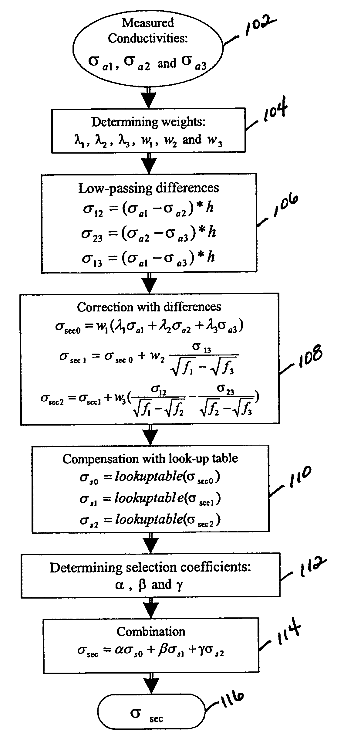
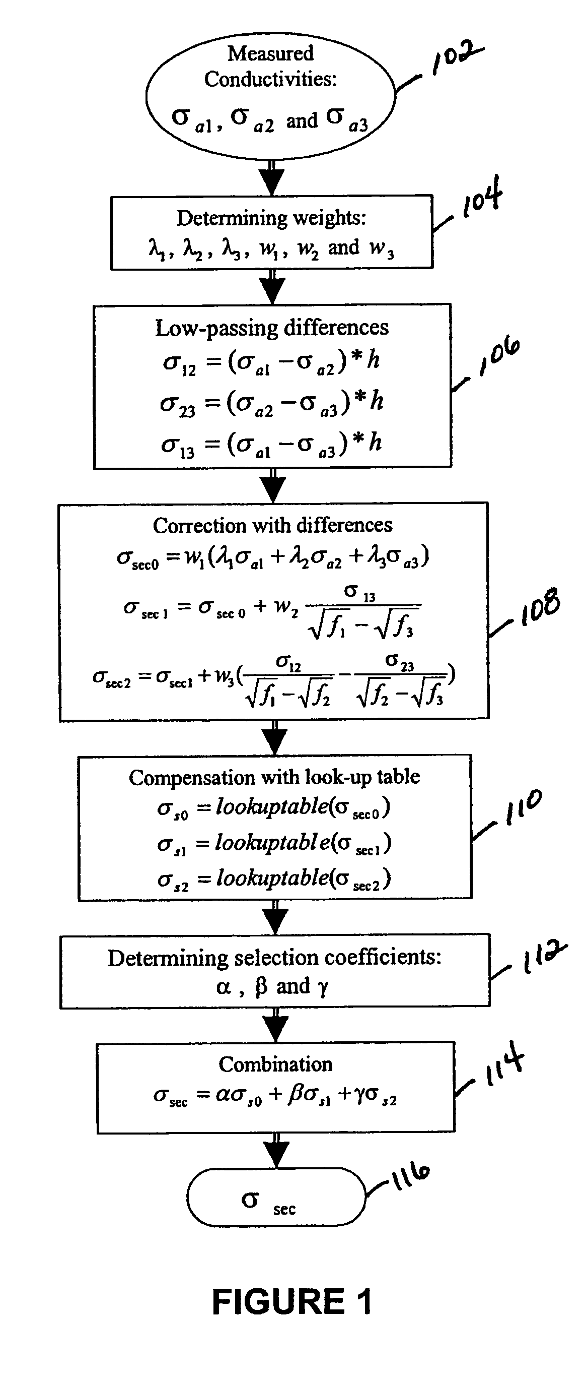
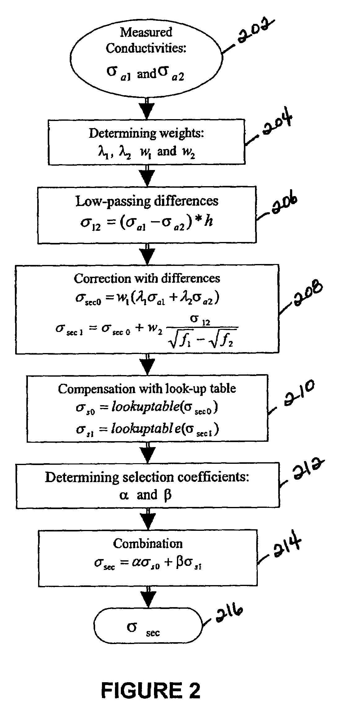
[0034]Referring now to the drawings, the details of exemplary embodiments of the present invention are schematically illustrated. Like elements in the drawing will be represented by like numbers, and similar elements will be represented by like numbers with a different lower case letter suffix.

[0035]Referring now to FIG. 15, depicted is an electromagnetic induction well logging instrument, generally represented by the numeral 10, is disposed in a wellbore 2 penetrating earth formations 4. The electromagnetic induction well logging instrument 10 is shown disposed in the wellbore 2 drilled through the penetrating earth formations 4. The electromagnetic induction well logging instrument 10 may be lowered into and withdrawn from the wellbore 2 by means of an armored electrical cable 6 or similar conveyance known in the art. The electromagnetic induction well logging instrument 10 may be, for example, assembled from three subsections: an auxiliary electronics unit 14 disposed at one end ...


PUM


Abstract

A system and method of correcting skin effect of conductivity measurements made by electromagnetic induction well logging instruments. A limited number of measurements using different frequencies may be used. The skin effect correction system and method is capable of processing a complex signal waveform but only requires the in-phase signal measurements which are then corrected for the skin effect value and the geometric factors of the apparent conductivity measurements, thus making the corrected measurements suitable for advanced processing with modern array-type induction logging tools.

Description

FIELD OF THE INVENTION[0001]The present invention relates generally to electromagnetic induction well logging instruments, and more particularly to a system and method of correcting skin effect of conductivity measurements made by the electromagnetic induction well logging instruments.BACKGROUND OF THE INVENTION TECHNOLOGY[0002]Electromagnetic induction logging instruments are used in the oil and gas industry to measure conductivity of geological formations penetrated by wellbores. A wellbore includes the openhole or uncased portion of an oil or gas well. A borehole may refer to the inside diameter of the wellbore wall, the rock face that bounds the drilled hole. The electromagnetic induction logging technology was first introduced in 1949, and more fully described by Henri G. Doll, “Introduction to Induction Logging and Application to Logging of Wells Drilled with Oil Based Mud,” Journal of Petroleum Technology, Vol. 1, No. 6, June 1949, pp. 148–162.[0003]In induction well logging,...

Claims


Application Information

Patent Timeline
Patent Type & Authority Patents(United States)
IPC IPC(8): G01V3/18G01V1/40G01V3/28
CPCG01V3/28
Inventor XIAO, JIAQI
Owner HALLIBURTON ENERGY SERVICES INC
Why Eureka
Try Eureka