Motor vehicle equipped with a diesel propulison engine

a technology of propulsion engine and motor vehicle, which is applied in the direction of engines, machines/engines, mechanical apparatus, etc., can solve the problems of increasing the amount of installation space, clogging of particle filter, and requiring burners, and achieves low cost and high reliability.

Inactive Publication Date: 2006-03-14
EMCON TECHNOLOGIES GERMANY (AUGSBURG) GMBH
View PDF7 Cites 9 Cited by
  • Summary
  • Abstract
  • Description
  • Claims
  • Application Information

AI Technical Summary

Benefits of technology

[0008]The object of the present invention is to create a motor vehicle of the above-described type equipped with an exhaust system including a discontinuously regenerating exhaust gas purification system. The regenerating exhaust gas purification system is low in cost and has technically simple subassemblies for the regenerating mode of the exhaust gas purification system, that require only a small amount of additional installation space, are low-maintenance, and highly reliable.

Problems solved by technology

Without the additive's, and depending on the soot composition, the particulate ignition temperature ranges between 470° C. and 600° C., by approximately 100° C., but in the long run cause the particulate filter to clog, necessitating cleaning.
However, there are several drawbacks to employing burners.
For one, they are expensive.
Additionally, an increased amount space is required for installation due to the integration of the comparatively large burner into the exhaust system.
Finally, the burner has a detrimental effect on the flow conditions within the exhaust pipe.
A particular disadvantage of this is the engineering and logistic effort concerning the storage of the low boiling organic fluid.
Furthermore, the regeneration of the diesel particulate filter utilizing this heating device requires exhaust gas temperatures above 450° C., which in modern diesel engines can only be attained under full load.
Additionally, given the conditions prevailing in non-purified exhaust gases the atomizer nozzles tend to clog, rendering the affected heating device non-functional within a short period of time and explaining why these systems never went into production.
These attempts were quickly aborted because the required electrical power was not able to be provided in conventional motor vehicles.

Method used


Image

  • Motor vehicle equipped with a diesel propulison engine
  • Motor vehicle equipped with a diesel propulison engine
  • Motor vehicle equipped with a diesel propulison engine

Examples


Embodiment Construction

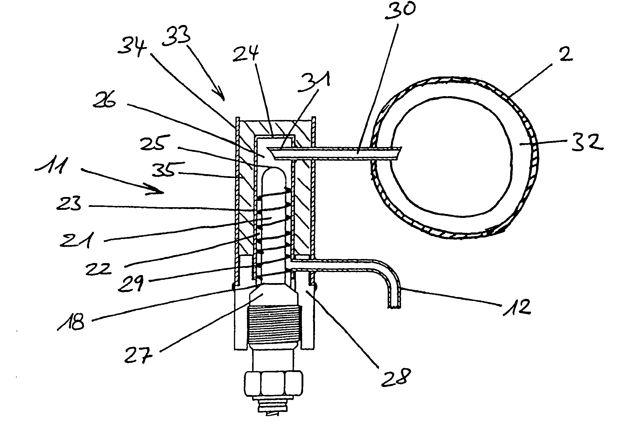
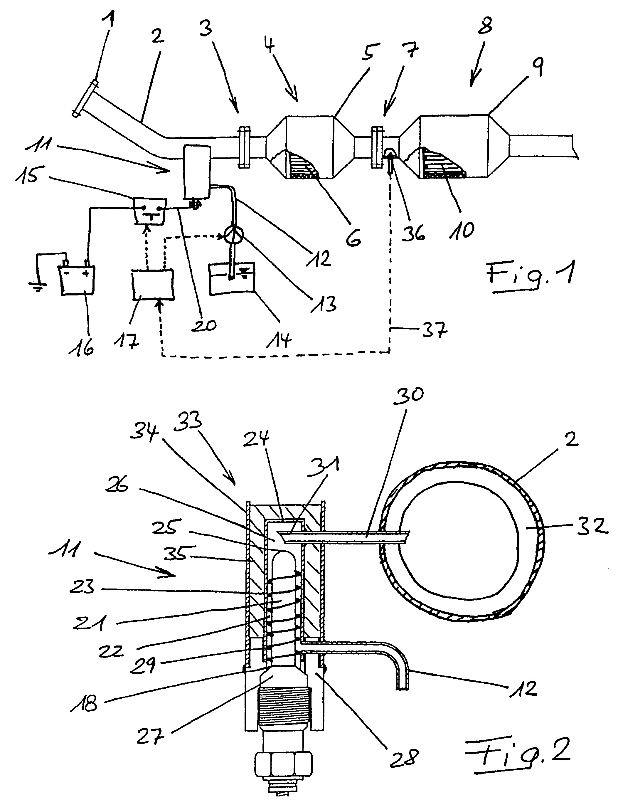
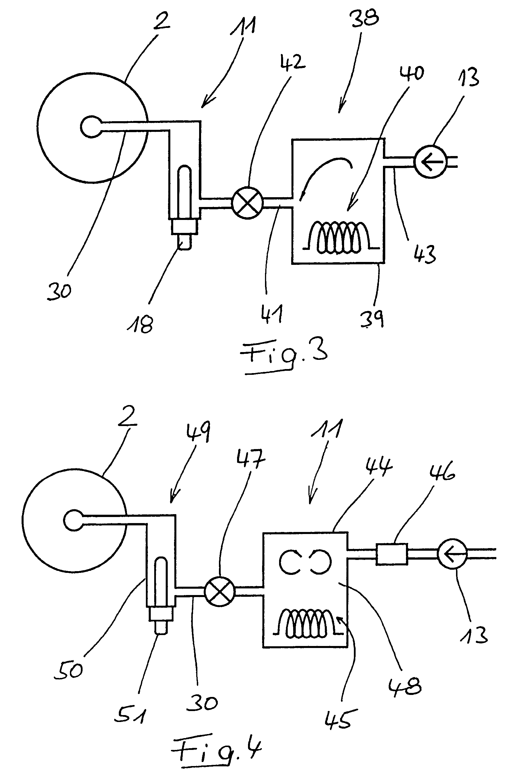
[0029]FIG. 1 illustrates a partial section of an exhaust system including a pre-tube 2 connectable to a manifold by a flange 1 and a catalytic converter assembly 4 connected to the pre-tube 2 by a flange connection 3. An oxidizing converter unit 6 is located in a catalytic converter housing 5 and a filter assembly 8 is connected to the catalytic converter assembly 4 with a flange connection 7. A particulate filter 10 is located in a particulate filter housing 9. Relatively close to the flange connection 3, the pre-tube 2 has a fuel evaporator unit 11 which feeds evaporated diesel fuel into the exhaust gas stream flowing through the pre-tube 2.

[0030]The fuel evaporator unit 11 is connected to a fuel tank 14 of the vehicle by a fuel line 12 having an integrated pump 13. Furthermore, the fuel evaporator unit 11 is connected to a power source 16 of the vehicle using a switch 15. The switch 15 is controlled in a generally known manner by a controller 17 which analyzes several input varia...


PUM


Abstract

A motor vehicle includes a diesel propulsion engine having an exhaust system. The exhaust system includes a discontinuously regenerating exhaust gas purification system including a catalytic converter unit for burning diesel fuel catalytically and a fuel evaporator unit connected upstream of the catalytic converter unit. The fuel evaporator unit includes an electrical heating element and is connected to the fuel tank of the vehicle by a fuel line. The fuel evaporator unit is spatial from any exhaust gas carrying components. A fuel vapor feeding channel upstream of the catalytic converter unit discharges into an exhaust gas carrying component and extends between the fuel evaporator unit and an exhaust gas carrying component.

Description

BACKGROUND OF THE INVENTION[0001]This invention relates generally to a motor vehicle equipped with a diesel propulsion engine including an exhaust system having a discontinuously regenerating exhaust gas purification system with a catalytic converter unit that burns diesel fuel catalytically. The continuously regenerating exhaust gas purification system may include diesel particulate filters and NOx, accumulating catalytic converters.[0002]To comply with environmental specifications, the exhaust gases of motor vehicles propelled by combustion engines are purified. Specifically, appropriate particulate filters are utilized to reduce the particulate emission of the exhaust gases of motor vehicles propelled by diesel engines. The particulate filters need to be periodically regenerated by burning off the particles accumulated on the filter surface. Due to the relatively low exhaust gas temperatures of modem diesel engines, to initiate regeneration, the exhaust gas temperature must be ra...

Claims


Application Information

Patent Timeline
Patent Type & Authority Patents(United States)
IPC IPC(8): F01N3/00F01N3/025F01N3/035F01N3/08F01N3/20
CPCF01N3/0253F01N3/035F01N3/0814F01N3/0842F01N3/36F01N2610/107F01N2240/30F01N2610/03F01N3/2033Y02A50/20
Inventor RANALLI, MARCOSCHMIDT, STEFANMAYR, ANDREASKLEMENT, JURGEN
Owner EMCON TECHNOLOGIES GERMANY (AUGSBURG) GMBH
Why Eureka
Try Eureka