Cathode ray tube apparatus having velocity modulation coil

Inactive Publication Date: 2006-03-14
PANASONIC CORP
View PDF10 Cites 6 Cited by
  • Summary
  • Abstract
  • Description
  • Claims
  • Application Information

AI Technical Summary

Benefits of technology

[0012]With the structure stated above, by the action of the magnet member that surrounds an outer circumference of the cathode ray tube in a manner to cover a position corresponding to a space between the first and second electrodes of the electr

Problems solved by technology

However, the color CRT apparatus of the 06-283113 publication is insufficient to achieve enough effect.
The magnetic member does strengthen this weak magnetic field but not to a sufficient level.
That is to say, the color CRT apparatus disclosed in the 06-283113 publication fails to improve the velocity mo

Method used


Image

  • Cathode ray tube apparatus having velocity modulation coil
  • Cathode ray tube apparatus having velocity modulation coil
  • Cathode ray tube apparatus having velocity modulation coil

Examples


Embodiment Construction

[0026]The following describes a preferred embodiment of the present invention, with reference to the drawings.

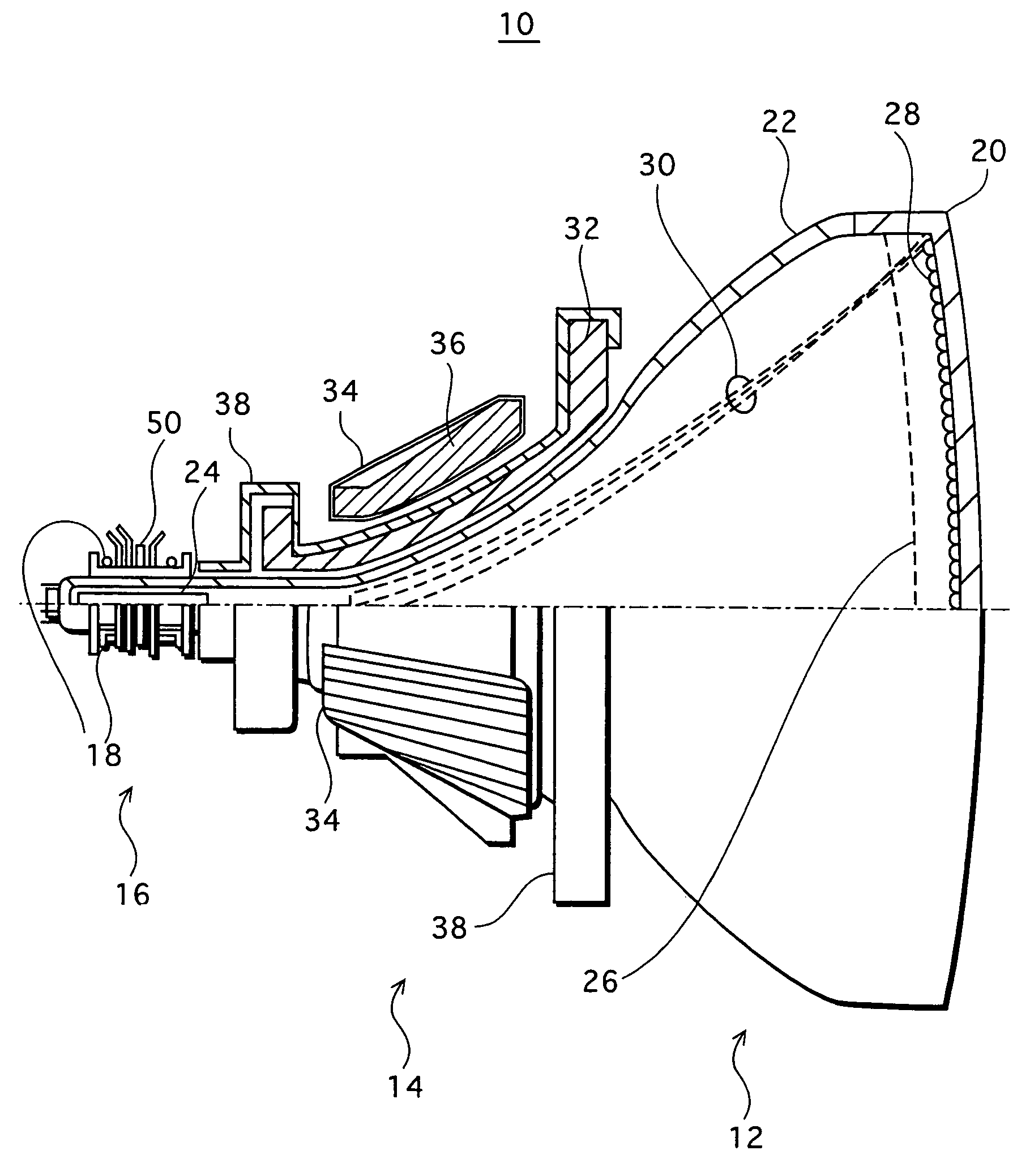
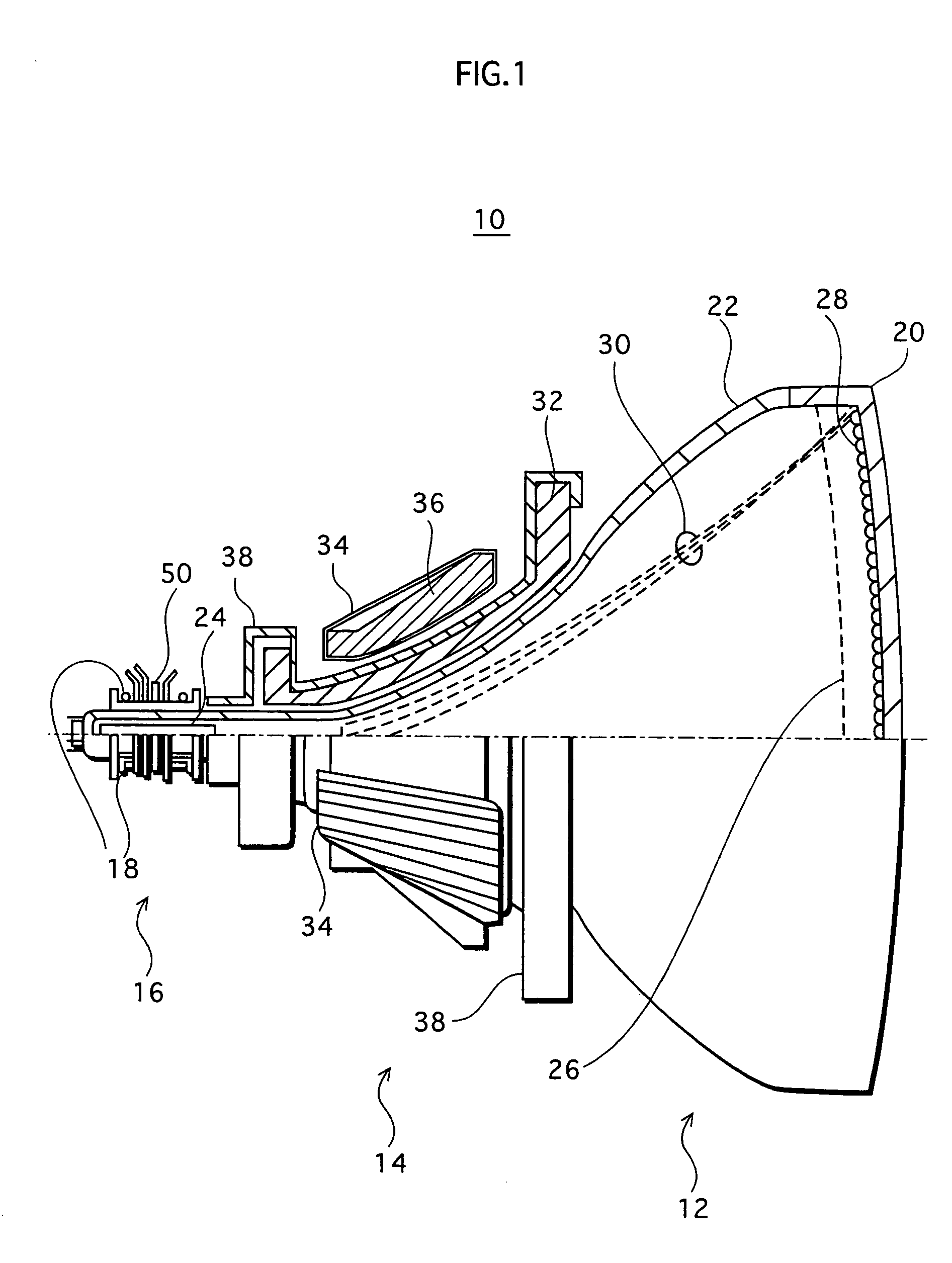
[0027]FIG. 1 is a half cross-sectional view showing a schematic structure of a color CRT apparatus 10.

[0028]As shown in FIG. 1, the color CRT apparatus 10 is mainly composed of a color CRT 12, a deflection yoke 14, a CPU (Convergence and Purity Unit) 16, and a velocity modulation coil 18.

[0029]The color CRT 12 is composed of a face panel 20 and a funnel 22 that are connected together to constitute a glass bulb. The glass bulb houses an inline-type electron gun (hereinafter, simply referred to as an “electron gun”) 24, a shadow mask 26, and so on.

[0030]On the inner surface the face pane 120 is a phosphor screen 28 formed with dots of red, green, and blue phosphors that are arranged in a regular order. The shadow mask 26 and the phosphor screen 28 are arranged substantially in parallel. The shadow masks 26 is provided with a number of beam passing holes, so that three electron...


PUM


Abstract

A CRT apparatus is composed of a CRT, a deflection yoke, a velocity modulation coil, and a magnetic member. The CRT includes a glass bulb made up of a panel and a funnel connected together and an electron gun housed within the glass bulb, and emits an electron beam from the electron gun toward a phosphor screen formed on an inner surface of the panel. The deflection yoke includes a horizontal deflection coil and a vertical deflection coil, and scans the electron beam over the phosphor screen. The velocity modulation coil is arranged outside the CRT, and modulates a velocity at which the electron beam is scanned horizontally. The magnetic member is arranged to surround an outer circumference of the CRT with the velocity modulation coil positioned therebetween, so as to cover a position corresponding to a space between axially aligned electrodes of the electron gun.

Description

[0001]This application is based on application No. 2003-78690 filed in Japan, the contents of which are hereby incorporated by reference.BACKGROUND OF THE INVENTION[0002](1) Field of the Invention[0003]The present invention relates to a cathode ray tube (CRT) apparatus for use in television sets and computer displays. More particularly, the present invention relates to a CRT apparatus having a velocity modulation coil.[0004](2) Description of the Related Art[0005]Edge enhancement is one scheme for realizing high image quality on television. To carry out edge enhancement processing, a television set is provided with a velocity modulation coil arranged at or near a neck portion of a CRT. The velocity modulation coil generates a magnetic field in a vertical direction to modulate the horizontal scanning velocity of an electron beam, thereby emphasizing the appearance of edges in images (See, for example, Examined Japanese Utility Model Application Publication No. S57-45650).[0006]With t...

Claims


Application Information

Patent Timeline
IPC IPC(8): H01J29/70H01J29/54H01J29/76
CPCH01J29/76H01J2229/5688A45F3/04A45F4/12
Inventor IWASAKI, KATSUYOTANIWA, KENICHIRO
Owner PANASONIC CORP
Why Eureka
Try Eureka