System and method generating a delayed clock output

a clock output and system technology, applied in the field of switches, can solve the problems of increasing the space required in the switch, occupying a large amount of space, and timing delays on both the receive signal and the transmit signal, so as to achieve the effect of substantially reducing the possibility of cross-coupling

Active Publication Date: 2006-03-14
AVAGO TECH INT SALES PTE LTD
View PDF1 Cites 18 Cited by
  • Summary
  • Abstract
  • Description
  • Claims
  • Application Information

AI Technical Summary

Benefits of technology

[0010]Embodiments of the invention provide a system and method for generating a 2 ns delayed clock signal without using a second PLL. Accordingly the space needed for a second PLL and associated circuitry is eliminated and the possibility of cross-coupling is substantially reduced.

Problems solved by technology

Accordingly, an 8-port Gigabit Switch requires 200 pins, which takes up a large amount of space.
However, the RGMII specification calls for a timing delay on both the receive signal and the transmit signal for each port.
However, a disadvantage of this conventional implementation is that it requires the 250 MHz PLL in addition to a 125 MHz PLL used to generate clock signals for the physical layers, thereby increasing the amount of space required within the switch.

Method used


Image

  • System and method generating a delayed clock output
  • System and method generating a delayed clock output
  • System and method generating a delayed clock output

Examples


Embodiment Construction

[0020]The following description is provided to enable any person having ordinary skill in the art to make and use the invention, and is provided in the context of a particular application and its requirements. Various modifications to the embodiments will be readily apparent to those skilled in the art, and the generic principles defined herein may be applied to other embodiments and applications without departing from the spirit and scope of the invention. Thus, the present invention is not intended to be limited to the embodiments shown, but is to be accorded the widest scope consistent with the principles, features and teachings disclosed herein.

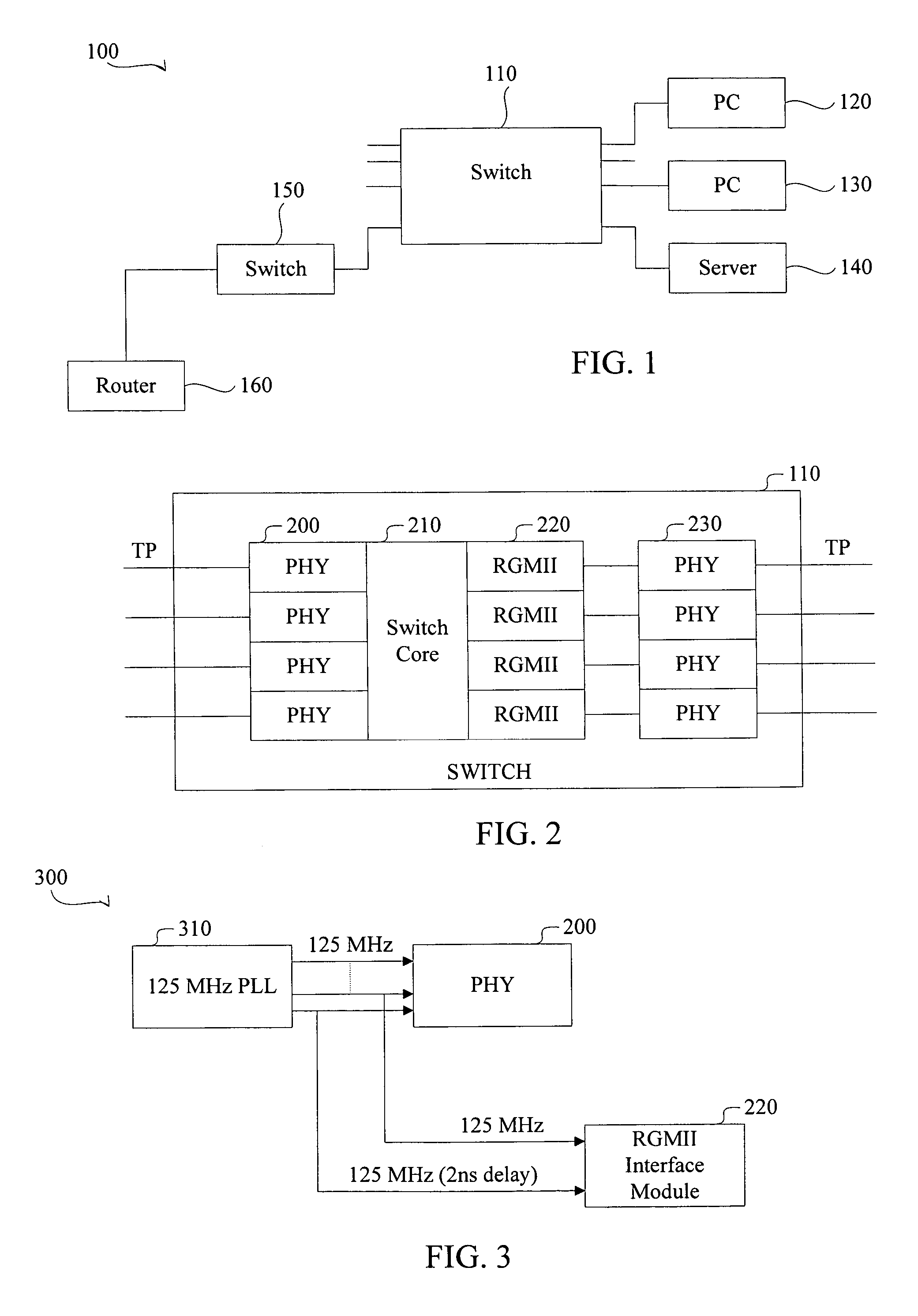
[0021]FIG. 1 is a block diagram illustrating a network system 100 in accordance with an embodiment of the present invention. The network system 100 includes 6 nodes: PCs 120 and 130, a server 140, a switch 110, a switch 150, and a router 160. The switch 150, the PC 120 and 130, and the server 140 are each communicatively coupled, via wire...


PUM


Abstract

The system and method generates two clock signals, one with a 2 ns delay with respect to the other, from a single PLL to enable a RGMII.

Description

PRIORITY REFERENCE TO PRIOR APPLICATION[0001]This application claims benefit of and incorporates by reference U.S. patent application Ser. No. 60 / 492,985, entitled “The Effective Implementation for the Egress Clock of RGMII,” filed on Aug. 7, 2003, by inventor Johnson Yen.BACKGROUND OF THE INVENTION[0002]1. Technical Field[0003]This invention relates generally to switches, and more particularly, but not exclusively, to a system and method for generating a delayed clock output for satisfying requirements of the Reduced Gigabit Media Independent Interface standard (RGMII).[0004]2. Description of the Related Art[0005]Networks, such as local area networks (i.e., LANs) and wide area networks (i.e., WANs, e.g., the Internet), enable a plurality of nodes to communicate with each other. Nodes can include computers, servers, storage devices, mobile devices, PDAs, wireless telephones, etc. Networks can include the nodes themselves, a connecting medium (wired, wireless and / or a combination of ...

Claims


Application Information

Patent Timeline
Patent Type & Authority Patents(United States)
IPC IPC(8): H03B1/00H03B27/00H03K5/00H03L7/099H03L7/18H04L12/46
CPCH04L12/46H04L12/40136H03L7/0996H03K2005/00241H03K2005/00286H03L7/18
Inventor YEN, JOHNSON
Owner AVAGO TECH INT SALES PTE LTD
Why Eureka
Try Eureka