Method and apparatus for parallel optical interconnection of fiber optic transmitters, receivers and transceivers

Inactive Publication Date: 2006-03-14
LUMENTUM OPERATIONS LLC
View PDF130 Cites 75 Cited by
  • Summary
  • Abstract
  • Description
  • Claims
  • Application Information

AI Technical Summary

Benefits of technology

[0010]Parallel fiber optic transmitter and receiver channels are implemented within a fiber optic module having LC connectors or other small form factor connectors. The fiber optic module is implemented with an optical element and an electrical element. The fiber optic module includes a printed circuit board (PCB) having one or more edges that serve as guide rails that can electrically and mechanically couple to one or more guide rail slots of a module cage. The module cage formed of a conductive material has the one or more guide rail slot which in themselves are conductive to electrically and mechanically couple to the one or more guide rails of the fiber optic module. The metallized module housing provides an internal electromagnetic interference shield which is coupled to the guide rail slot of a module cage and a ground plane of a host or daughter card printed circuit board (PCB) as well as to a chassis ground. The grounding to the chassis is achieved by the module cage tabs which protrude from the cage housing and can electrically couple the internal electromagnetic interference shield and the one or more guide rail slots to the chassis ground. The cage is therefore in contact directly with the system chassis both mechanically and electrically for grounding. The arrangement allows fiber optic module to “hot plug” or be physically inserted and withdrawn during system operation without causing damage to either the fiber optic module or the system.

Problems solved by technology

Because of the high modulation frequencies utilized in fiber optic communication, crosstalk between receive and transmit signals and electromagnetic interference (EMI) is of concern.
However, the tightly packed VCSELs in the VCSEL array having such small spacing there between introduces some challenges.
One challenge which is difficult to overcome is separately monitoring the output power of each VCSEL in the VCSEL array when they are so tightly spaced and packaged together.
Additionally, the close spacing of the VCSELs in a VCSEL array aggravates the difficulty of placing EE components and interconnections on a printed circuit board.
Additionally, the close spacing of VCSELs in the VCSEL array complicates any optical alignment needed between EE and OE components and the fiber optic cable.
To provide five dimensional alignment, expensive packaging and packaging tools are required.
Another disadvantage to VCSEL arrays is that power output is highly localized due to the tightly spaced VCSELs in the VCSEL arrays.
Otherwise, harm may result to a user's eyes if the user accidentally looks into the laser beams from the VCSEL array.

Method used


Image

  • Method and apparatus for parallel optical interconnection of fiber optic transmitters, receivers and transceivers
  • Method and apparatus for parallel optical interconnection of fiber optic transmitters, receivers and transceivers
  • Method and apparatus for parallel optical interconnection of fiber optic transmitters, receivers and transceivers

Examples


Embodiment Construction

[0021]In the following detailed description of the present invention, numerous specific details are set forth in order to provide a thorough understanding of the present invention. However, it will be obvious to one skilled in the art that the present invention may be practiced without these specific details. In other instances well known methods, procedures, components, and circuits have not been described in detail so as not to unnecessarily obscure aspects of the present invention.

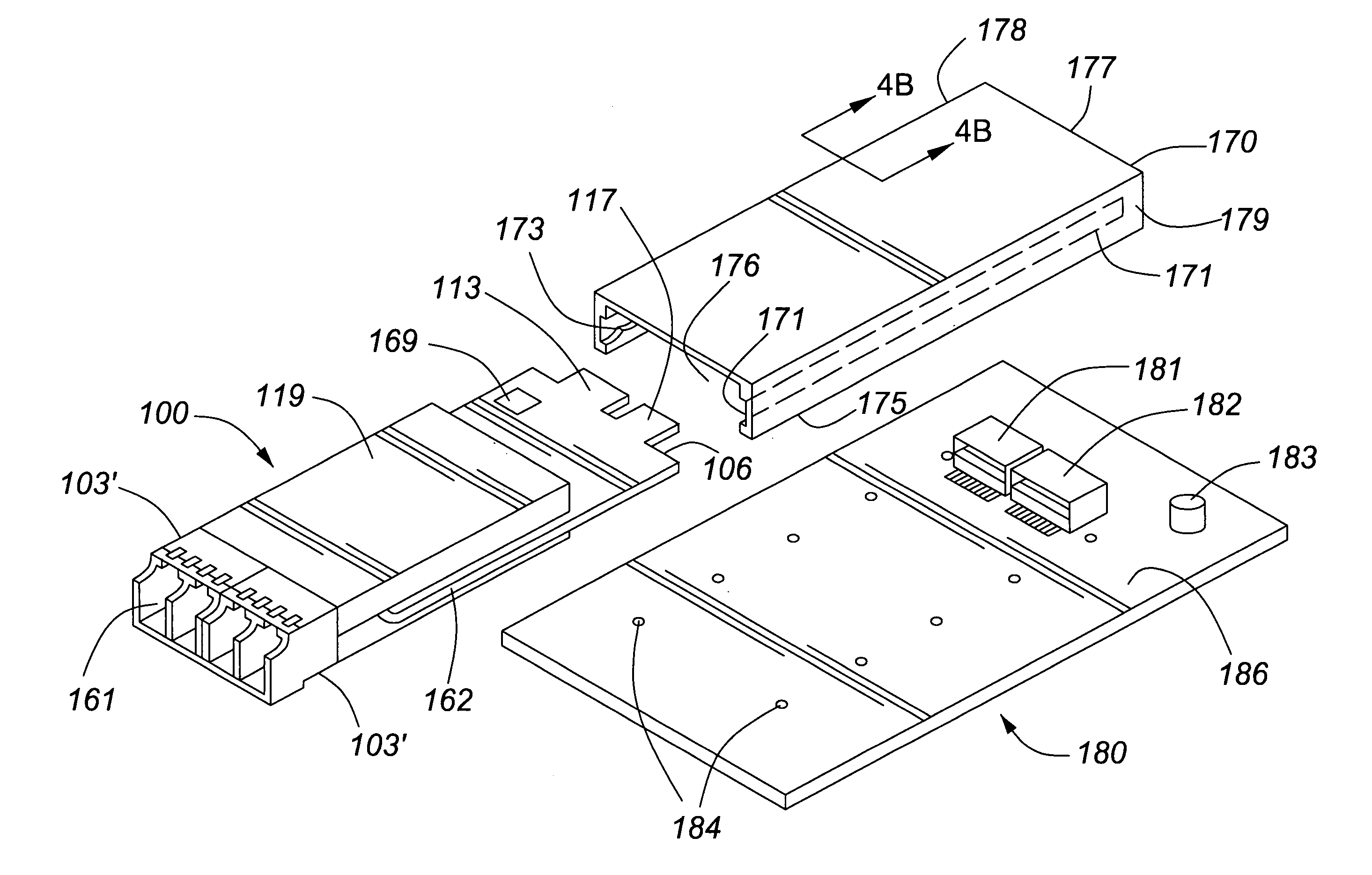
[0022]The present invention includes a method, apparatus and system for parallel optical interconnection of fiber optic transmitters, receivers, and / or transceivers.

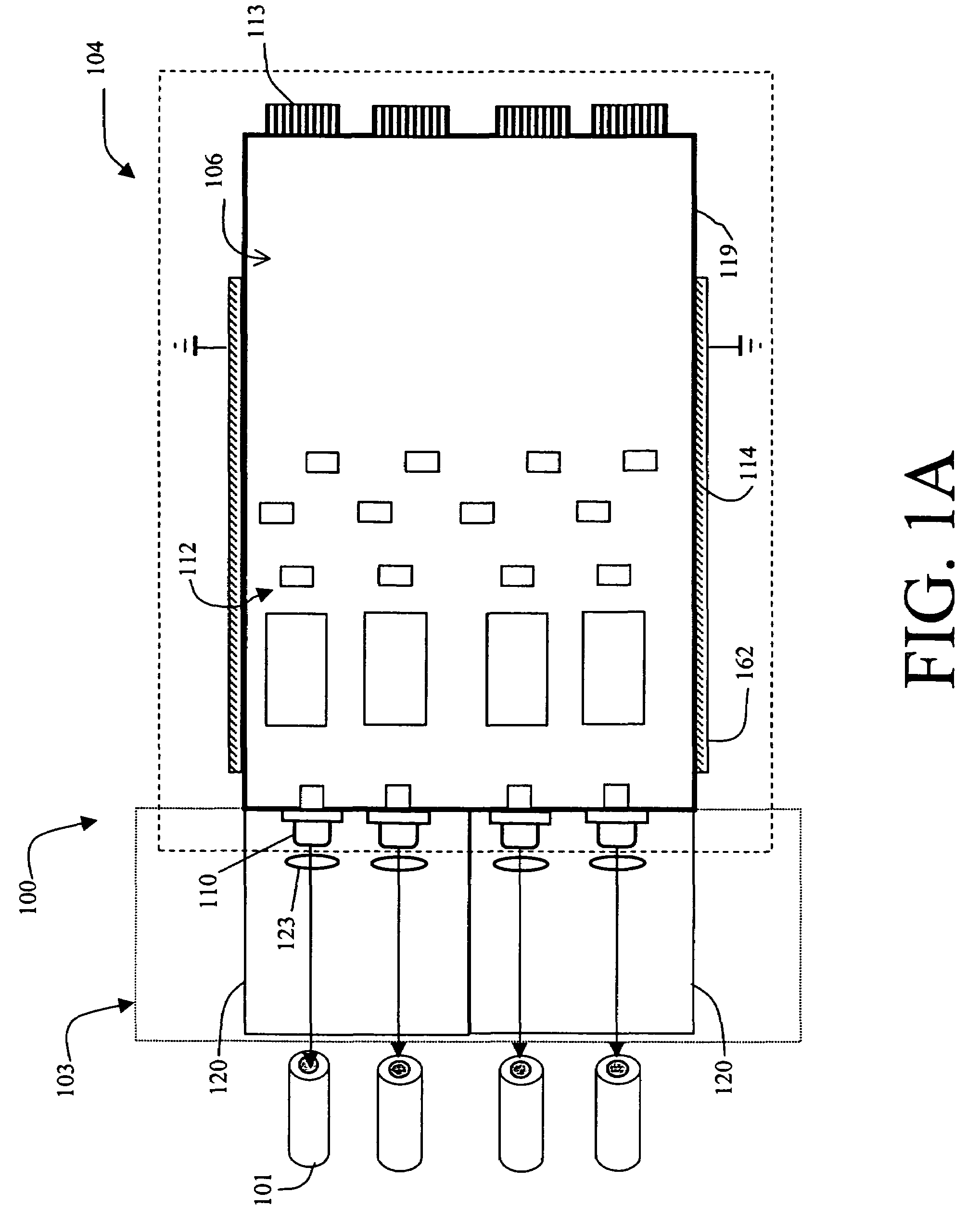
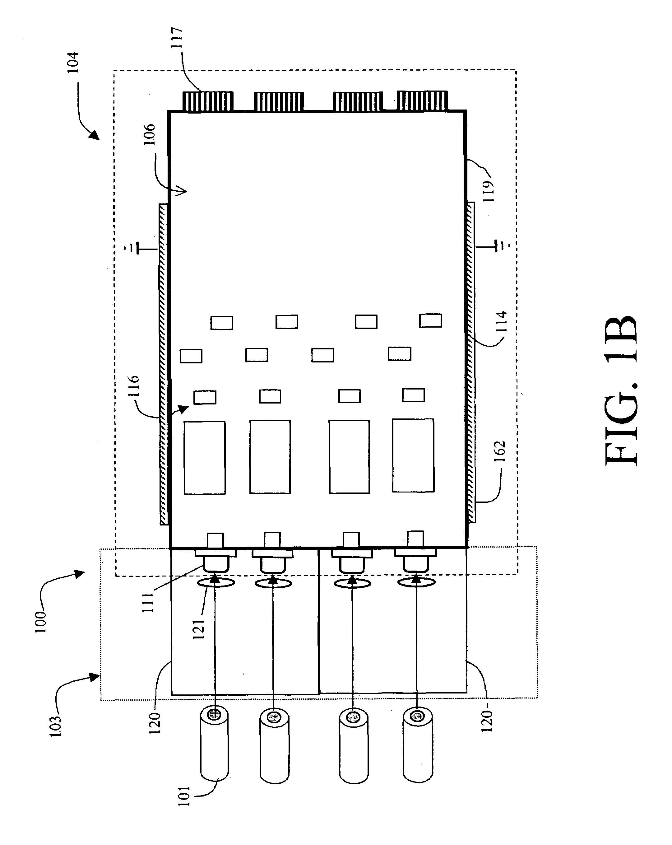
[0023]Referring now to FIG. 1A, a simplified cutaway view of a first embodiment of the present invention is illustrated. FIG. 1A illustrates a fiber optic module 100 (a fiber optic transmitter, receiver, or transceiver module) for coupling to a plurality of fiber optic cables 101. The fiber optic cable 101 may be individual cables or a ribbo...


PUM


Abstract

A multichannel fiber optic module has an electromagnetic shield surrounding high frequency electrical components which is electrically and mechanically coupled to one or more guide rails near edges of a printed circuit board. The one or more guide rails of the printed circuit board include a ground trace on the top and / or bottom surfaces of the printed circuit board. The fiber optic module can be hot inserted into a module cage which has guide rail slots for mating with the guide rails of the fiber optic module. Through the guide rail slots, electromagnetic radiation from the fiber optic module is shunted to a ground plane to which the module cage is coupled on a host chassis ground. Standard singular fiber receptacles are used for the parallel data link modules to allow field cable termination.

Description

CROSS REFERENCE TO RELATED APPLICATION[0001]This application claims the benefit and is a continuation-in-part of U.S. patent application Ser. No. 09 / 321,308, filed on May 27, 1999 now U.S. Pat. No. 6,901,221 by Wenbin Jiang et al. which is hereby incorporated by reference and also claims the benefit of and is a continuation-in-part of U.S. patent application Ser. No. 09 / 320,409, filed on May 26, 1999 now U.S. Pat. No. 6,213,651 by Wenbin Jiang et al. which is hereby incorporated by reference, both of which are to be assigned to E2O Communications, Inc.FIELD OF THE INVENTION[0002]This invention relates generally to light coupling devices. More particularly, the invention relates to fiber optic modules.BACKGROUND OF THE INVENTION[0003]Fiber optic modules interface optical fibers to electronic circuitry transducing communication by light or photons with communication by electrical signals. A fiber optic module may be a fiber optic receiver, transmitter or transceiver including both rec...

Claims


Application Information

Patent Timeline
IPC IPC(8): H04B10/00G02B6/42H05K1/02H05K1/14
CPCG02B6/4204G02B6/4214G02B6/4246G02B6/4292H04B10/801G02B6/4277H05K1/14H05K1/0274G02B6/4245G02B6/4261G02B6/4284G02B6/428G02B6/4244
Inventor JIANG, WENBINLEE, HSING-CHUNGCHENG, MIN-WENSHIEH, CHAN-LONGWEI, CHENG PINGDAIR, EDWIN D.
Owner LUMENTUM OPERATIONS LLC
Why Eureka
Try Eureka