Exhaust purification apparatus and method for internal combustion engine

a technology of exhaust purification apparatus and internal combustion engine, which is applied in the direction of machines/engines, automatic control of ignition, electrical control, etc., can solve the problems of not being effectively utilized, the total time duration required to end the poisoning release is long, and the fuel economy cannot be suppressed. , to achieve the effect of worsening the fuel economy

Inactive Publication Date: 2006-03-21
NISSAN MOTOR CO LTD
View PDF15 Cites 42 Cited by
  • Summary
  • Abstract
  • Description
  • Claims
  • Application Information

AI Technical Summary

Benefits of technology

[0006]It is desirable that the poisoning release is finished in a time period as short as possible since the poisoning release c

Problems solved by technology

In spite of this fact, this is not effectively utilized.
Therefore, a total time duration to end t

Method used


Image

  • Exhaust purification apparatus and method for internal combustion engine
  • Exhaust purification apparatus and method for internal combustion engine
  • Exhaust purification apparatus and method for internal combustion engine

Examples


Embodiment Construction

[0030]Reference will hereinafter be made to the drawings in order to facilitate a better understanding of the present invention.

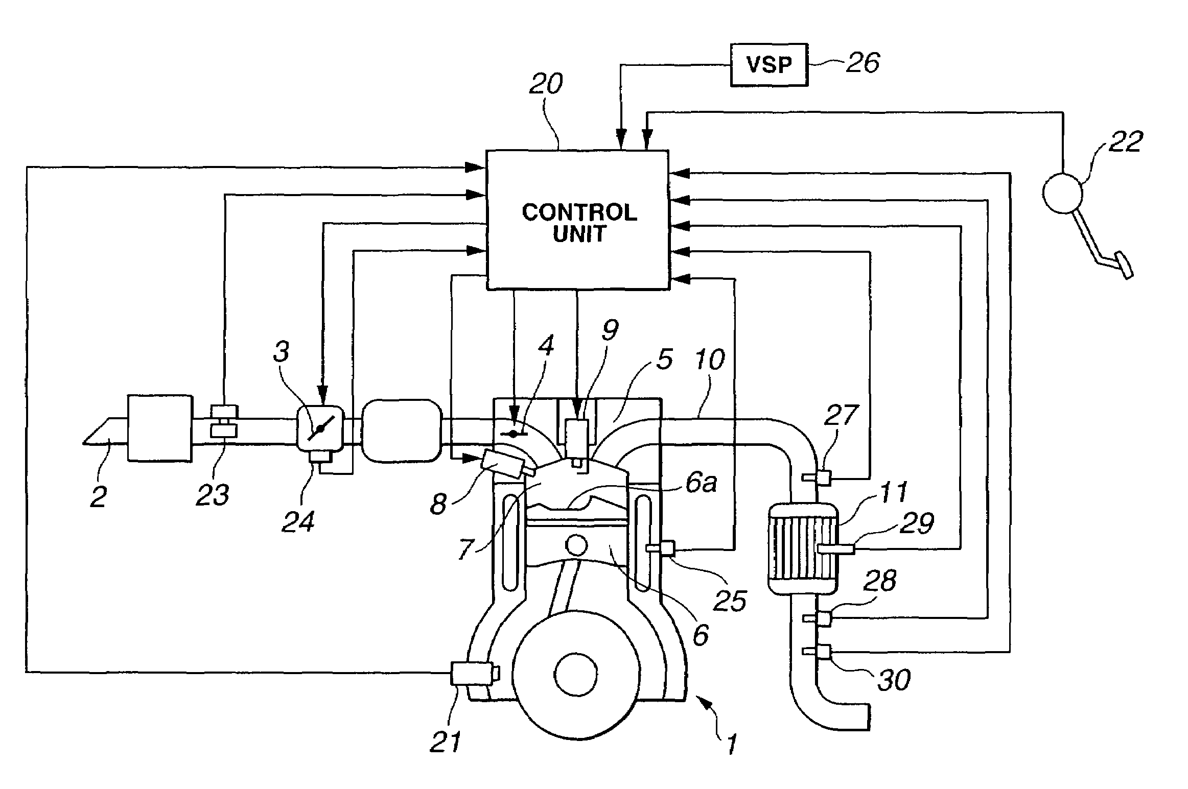
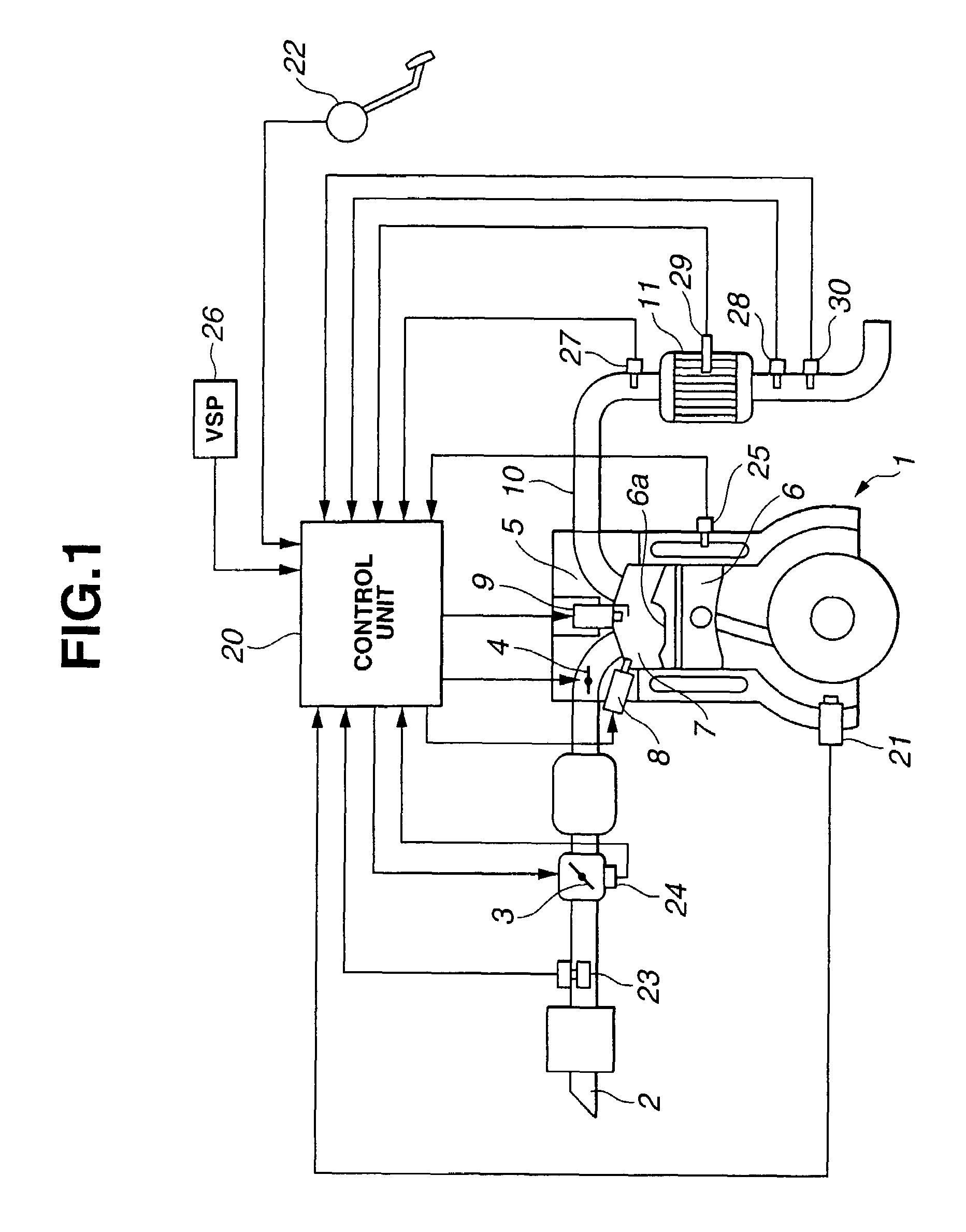
[0031]FIG. 1 shows a rough configuration view of an internal combustion engine to which an exhaust purification apparatus according to the present invention is applicable. Engine denoted by 1 has an intake passage 2 in which a throttle valve 3 to control an intake air quantity is mounted. Throttle valve 3 is an electronically controlled throttle valve activated by means of an actuator such as an electric motor (DC motor). A drive signal from a control unit (or also referred to as a controller) 20 drives throttle valve 3 to be opened or closed. A swirl control valve (SCV) 4 is disposed at a downstream side from a manifold section branched to each cylinder. Another drive signal from control unit 20 drives swirl control valve 4 to be opened or closed. A fuel injector (or called, a fuel injection valve) 8 is exposed to a combustion chamber 7 of each cylinder of...


PUM


Abstract

In exhaust purification apparatus and method for an internal combustion engine having an exhaust gas purification catalyst disposed in an exhaust passage of the engine, a poisoning release control of the exhaust gas purification catalyst is executed when a predetermined condition is established, the poisoning release control including a normal mode and an exhaust gas composition mode before the normal mode, and a manipulation parameter (for example, an ignition timing) of the engine related to an exhaust gas composition is manipulated in such a manner that a hydrogen concentration in the exhaust gas in the exhaust gas composition mode is higher than that in the normal mode.

Description

BACKGROUND OF THE INVENTION[0001]1. Field of the Invention[0002]The present invention relates to exhaust purification apparatus and method for an internal combustion engine, the engine having an exhaust passage in which an exhaust (or exhaust gas) purification catalyst is mounted. The exhaust purification apparatus and method according to the present invention perform a poisoning release control of the exhaust purification catalyst when a predetermined condition is established.[0003]2. Description of the Related Art[0004]A Japanese Patent Application First Publication No. 2001-271685 published on Oct. 5, 2001 exemplifies previously proposed catalyst temperature controlling apparatus and method for a direct cylinder fuel injection internal combustion engine.[0005]In the previously proposed catalyst temperature controlling method and apparatus, while, against a poisoning of sulfur of an NOx trap catalyst, a poisoning release thereagainst is being executed, an air-fuel ratio within a c...

Claims


Application Information

Patent Timeline
IPC IPC(8): F01N3/00F02P5/15F01N3/20F01N3/24F02D37/02F02D41/02F02D41/34F02D41/40F02D43/00F02D45/00
CPCF02D37/02F02D41/0245F02D41/027F02D41/402F02D41/1463Y02T10/26F02D2200/0802Y02T10/44F02P5/1502Y02T10/12Y02T10/40
Inventor YOSHIDA, IWAO
Owner NISSAN MOTOR CO LTD
Why Eureka
Try Eureka