Dust collection system for a masonry saw

a technology of dust collection system and masonry saw, which is applied in the field of masonry saw dust collection system, can solve the problems of polluting factor, exposed or finished product side of a cmu, requiring more labor and more water for cleaning, and achieve the effect of reducing the amount of dust particles

Active Publication Date: 2006-03-21
JPL GLOBAL
View PDF21 Cites 42 Cited by
  • Summary
  • Abstract
  • Description
  • Claims
  • Application Information

AI Technical Summary

Benefits of technology

[0005]The object of the present invention is to provide a dust collection system for masonry saws that minimizes the amount of dust particles released into the atmosphere during the cutting process, both for the protection of the worker and the protection of the environment.
[0007]The invention proposes to increase the area of dust collection to accommodate a large variety of masonry materials and to provide a three-point dust collection system effective over the increased area.
[0009]The collection system is comprised of three dust and debris collection points or areas. First, a vacuum hood assembly or shroud is attached to the back of the movable saw table and connected to a vacuum source. Second, the table surface is provided with a grating and a vacuum chamber below the grating, also connected to a vacuum source, to act as a secondary dust collection area. Third, a heavy debris collection chamber is provided below the table vacuum chamber. These three areas work in conjunction to effectively capture the dust and debris produced in the cutting process. The vacuum table and vacuum hood or shroud assembly are of such design that the volume of dust from the blade in the cutting process is compatible with the velocity of the vacuum systems used to capture the volume of dust created.

Problems solved by technology

The method works well, but has drawbacks in situations where the waste water from the wet cutting is a polluting factor.
Another disadvantage of wet cutting occurs on the exposed or finished product side of a CMU.
This requires more labor and more water for the cleaning process, which in turn wastes man-hours and dollars, as well as creating more waste water run off.
While masonry saws and the movable tables used with them have been around for some time, the art has not taken the next logical step, which is to protect the worker and the environment from the dust created from this type of work.
Some attempts have been made to solve this problem, with limited results.
This apparatus is limited in its scope of use to tile, pavers, bricks and other small masonry units.
The sawdust removal system is also limited in that the area of dust collection is inadequate.
The drawback of that in the masonry field is that much dust would still be released into the surrounding work area if employed in the cutting of large masonry units.

Method used


Image

  • Dust collection system for a masonry saw
  • Dust collection system for a masonry saw
  • Dust collection system for a masonry saw

Examples


Embodiment Construction

[0018]The following is a detailed description of one embodiment of the invention presently deemed by the inventor to be the best mode of carrying out his invention.

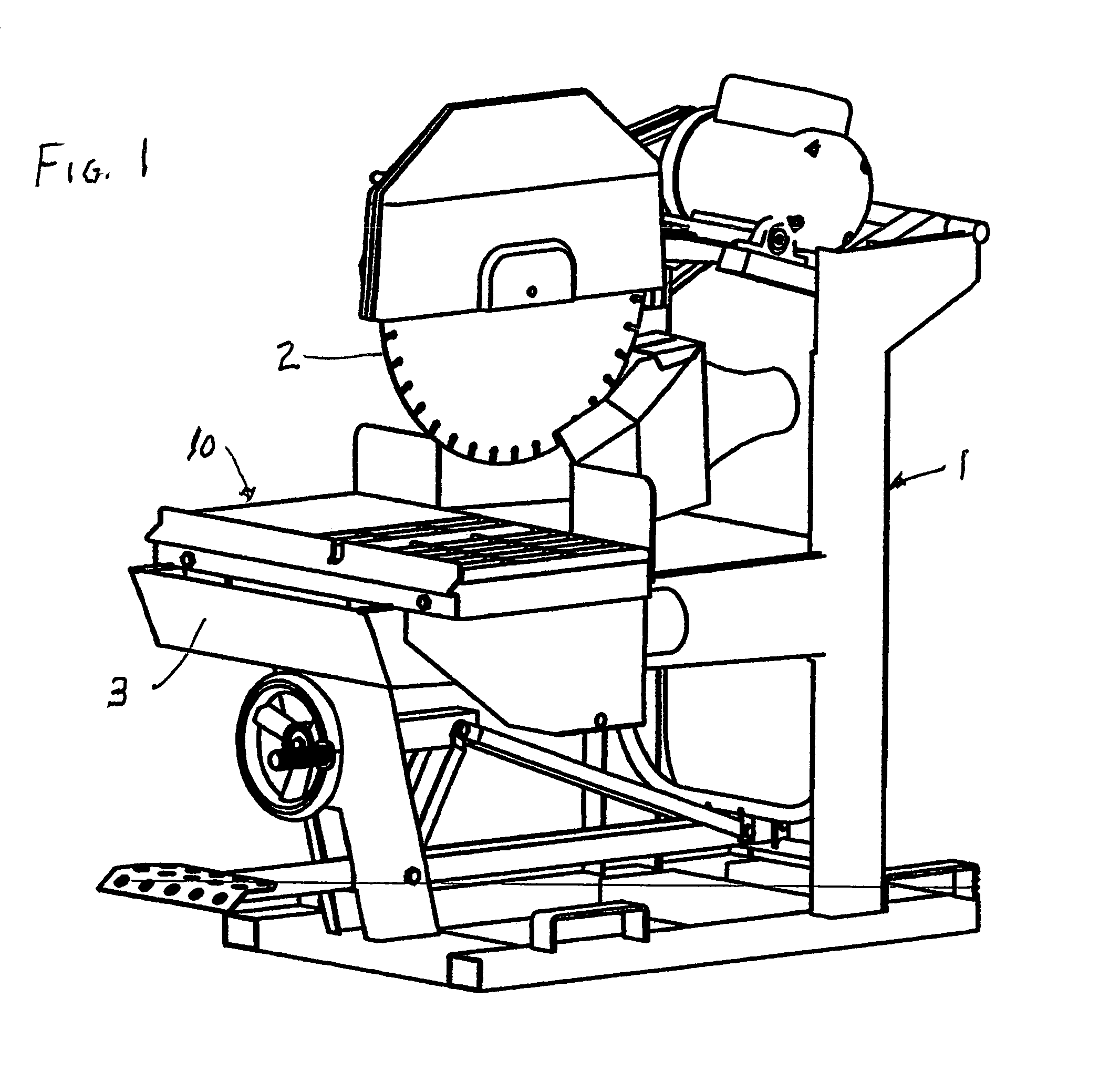
[0019]Referring to the drawings, particularly to FIG. 1, a conventional, commercially available masonry saw, indicated generally at 1, having a saw blade 2 and a supporting frame or tray 3 is shown as equipped with a preferred embodiment of the dust collection system 10 of the present invention.

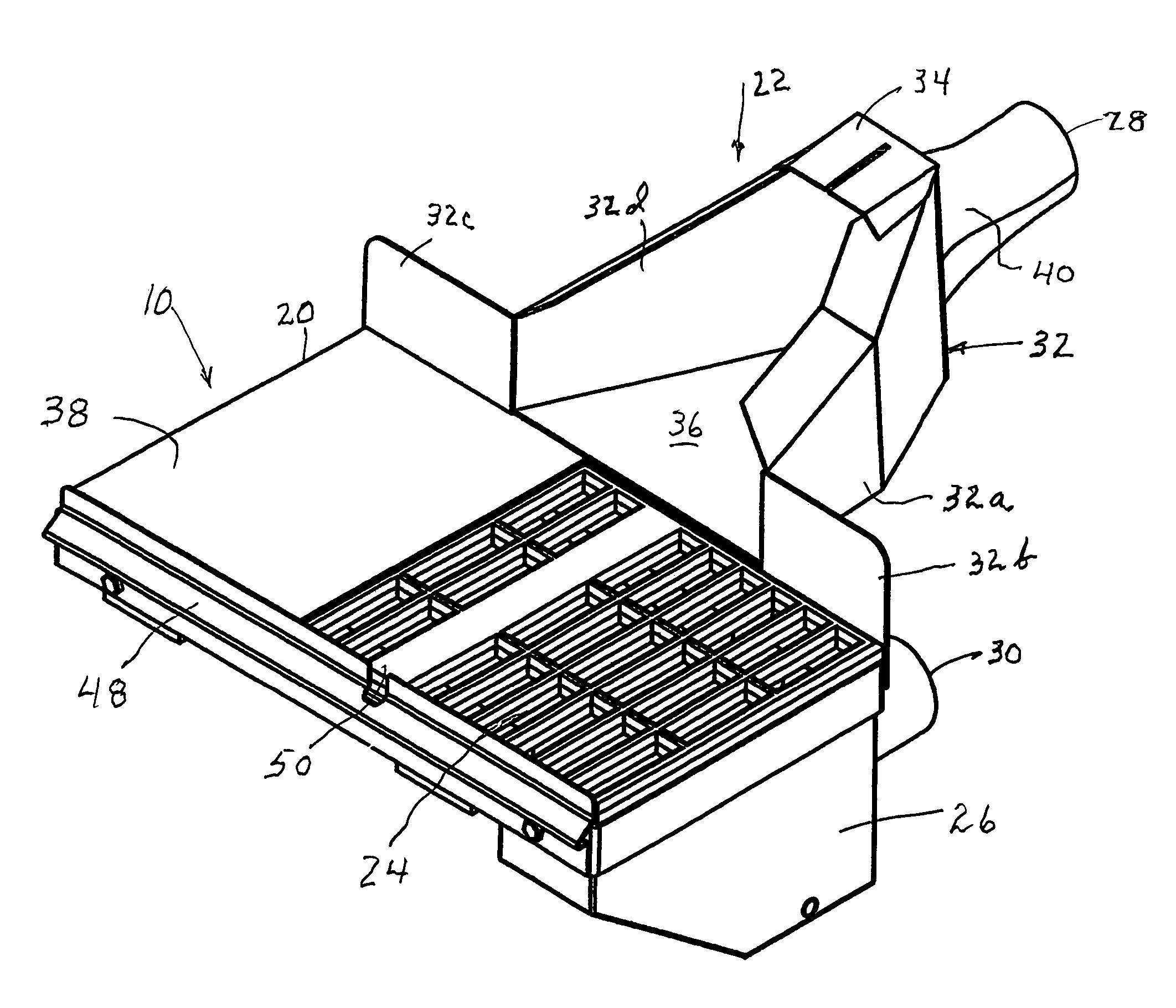
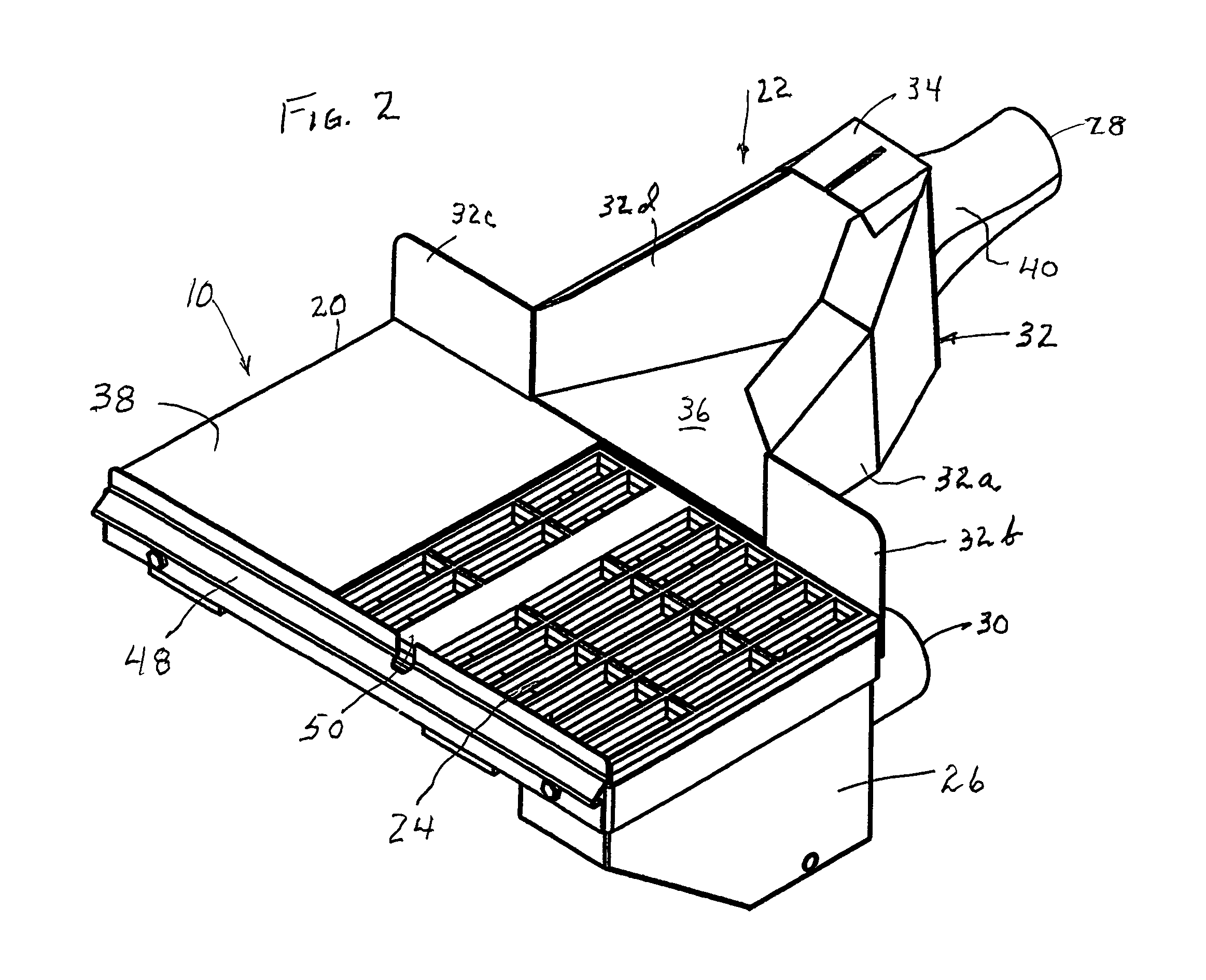
[0020]Referring to FIG. 2, the dust collection system 10 comprises a movable masonry saw table 20, a vacuum shroud or hood assembly 22, a grated table surface24 and underlying vacuum chamber 52, a heavy debris collection chamber 26, a hood vacuum intake 28 and a table vacuum intake 30. The table 20 is slidably supported on the saw frame 3 for movement toward and away from the blade 2 by wheels 44 located at the four corners of the table, as is conventional in the art.

[0021]The hood or shroud assembly 22 includes rigid skirting 32 c...


PUM

PropertyMeasurementUnit
angleaaaaaaaaaa
angleaaaaaaaaaa
angleaaaaaaaaaa

Abstract

Dust and debris resulting from the sawing or cutting of concrete masonry units, blocks, bricks, tiles and other masonry products is collected via a three point dust and debris collection system. A movable work supporting table for cooperation with a masonry saw has a grated surface, a vacuum chamber below the grated surface acting as one collection point or area, a heavy debris collection chamber below and in communication with the table vacuum chamber acting as another collection point or area, and a shroud or hood assembly extending rearwardly from the table adapted to extend about the sides and rear of the saw blade and including a vacuum chamber acting as a primary collection point or area. The system is highly effective in achieving dust capture.

Description

FIELD OF THE INVENTION[0001]This invention relates to masonry saws, and in particular, to a dust collection system for saws used for the cutting of concrete block, brick, tile and the like.BACKGROUND OF THE INVENTION[0002]In the cutting of masonry products, such as concrete masonry units (“CMU”) at a job site, much dust is released into the air as a result of the cutting process. Saws create dust at various points on the saw blade, releasing the dust into the environment as well as into the face of the worker. To minimize the release of the extreme amounts of dust into the air, various methods have been introduced over the years. Wet cutting is one of the methods. This allows water to be used at the cut to keep the dust from dispersing. The method works well, but has drawbacks in situations where the waste water from the wet cutting is a polluting factor. Another disadvantage of wet cutting occurs on the exposed or finished product side of a CMU. After wet cutting, the CMU needs to ...

Claims


Application Information

Patent Timeline
Patent Type & Authority Patents(United States)
IPC IPC(8): B28D1/04B23Q11/00B28D7/02B28D7/04
CPCB23Q11/0046B28D7/04B28D7/02
Inventor GUTH, PAUL W.
Owner JPL GLOBAL
Why Eureka
Try Eureka