White light emitting phosphor blend for LED devices

a technology of phosphor blend and led devices, which is applied in the direction of energy-saving lighting, sustainable buildings, lighting and heating apparatus, etc., can solve the problems of led color output deviating from the desired parameters, led power applied to the led frequently deviating from the desired value, and color output of the system to appear non-whi

Inactive Publication Date: 2006-03-21
GE LIGHTING SOLUTIONS LLC
View PDF28 Cites 78 Cited by
  • Summary
  • Abstract
  • Description
  • Claims
  • Application Information

AI Technical Summary

Problems solved by technology

However, the blue LED—YAG:Ce phosphor white light illumination system suffers from the following disadvantages.
Furthermore, even if the band gap of a particular LED has the desired width, during LED operation the power applied to the LED frequently deviates from the desired value.
This also causes the LED color output to deviate from the desired parameters.
A significant deviation from the desired parameters may cause the color output of the system to appear non-white (i.e., bluish or yellowish).
Furthermore, the color output of the blue LED—YAG:Ce phosphor system varies greatly due to frequent, unavoidable, routine deviations from desired parameters (i.e., manufacturing systematic variations) during the production of the LED lamp because the color output of the blue LED—YAG:Ce phosphor system is very sensitive to the thickness of the phosphor.
Unfortunately, it is difficult to control the precise thickness of the phosphor during large scale production of the blue LED—YAG:Ce phosphor system.
Variations in phosphor thickness often result in the system output being unsuitable for white light illumination applications, causing the color output of the system to appear non-white (i.e., bluish or yellowish), which leads to an unacceptably low blue LED—YAG:Ce phosphor system manufacturing yield.
The blue LED—YAG:Ce phosphor system also suffers from the halo effect due to the separation of blue and yellow light.

Method used


Image

  • White light emitting phosphor blend for LED devices
  • White light emitting phosphor blend for LED devices
  • White light emitting phosphor blend for LED devices

Examples


example 1

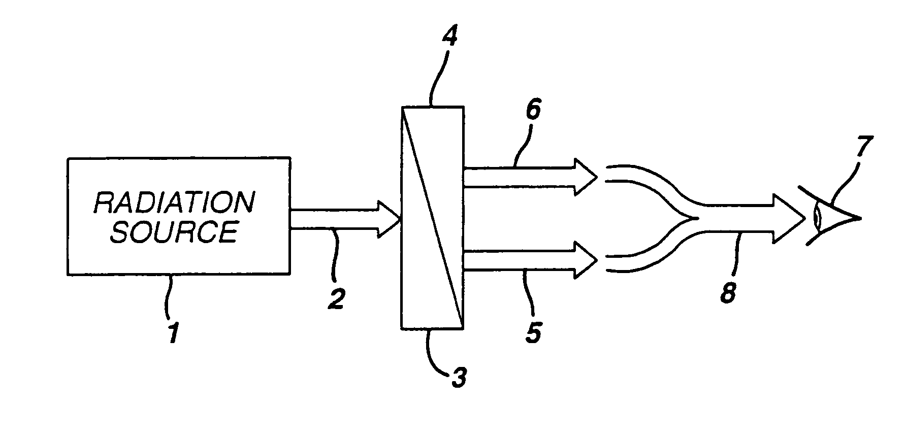
[0079]A first (Sr0.8Eu0.1Mn0.1)2P2O7 phosphor was prepared by blending SrHPO4, MnCO3, Eu2O3 and (NH4)HPO4 powders to form a starting powder mixture. The (NH4)HPO4 was added in an amount comprising 2% in excess of the stoichiometric ratio per mole of the first phosphor produced. The starting powder mixture was then heated in air at about 600° C. for 1 hour. The resulting powder was then re-blended and subsequently fired in a reducing atmosphere comprising nitrogen and 0.5% hydrogen at about 1000° C. for eight hours to form a calcined phosphor body or cake. The solid phosphor cake was converted to a first phosphor powder by wet milling and subsequent drying.

[0080]The first phosphor powder was blended with a commercially obtained SAE phosphor powder in a ratio of 89:11 by weight to obtain a phosphor powder blend or mixture. The phosphor powder blend was irradiated with a light source having a peak emission wavelength of 405 nm. The phosphor emission appeared white and its CIE color coo...

example 2

[0081]The experiment of Example 1 was repeated, except that a radiation source had a peak emission wavelength of 380 nm and the phosphor powder blend contained a 77:23 ratio by weight of strontium pyrophosphate to SAE. The phosphor emission appeared white and its CIE color coordinates were determined to be x=0.39 and y=0.42 from photometric calculations. The color coordinates are indicative of a color output which appears white to a human observer.


PUM

PropertyMeasurementUnit
peak emission wavelengthaaaaaaaaaa
wavelengthaaaaaaaaaa

Abstract

There is provided a white light illumination system including a radiation source, a first luminescent material having a peak emission wavelength of about 570 to about 620 nm, and a second luminescent material having a peak emission wavelength of about 480 to about 500 nm, which is different from the first luminescent material. The LED may be a UV LED and the luminescent materials may be a blend of two phosphors. The first phosphor may be an orange emitting Eu2+, Mn2+ doped strontium pyrophosphate, (Sr0.8Eu0.1Mn0.1)2P2O7. The second phosphor may be a blue-green emitting Eu2+ doped SAE, (Sr0.90-0.99 Eu0.01-0.1)4Al14O25. A human observer perceives the combination of the orange and the blue-green phosphor emissions as white light.

Description

CORRESPONDING RELATED APPLICATIONS[0001]The present application is a continuation application of parent U.S. patent application Ser. No. 09 / 571,379, filed on May 15, 2000. Now U.S. Pat. No. 6,501,100.STATEMENT REGARDING FEDERALLY SPONSORED RESEARCH OR DEVELOPMENT[0002]The U.S. Government may have certain rights in this invention pursuant to grant number 70NANB8H4022 from the NIST.BACKGROUND OF THE INVENTION[0003]This invention relates generally to a white light illumination system, and specifically to a ceramic phosphor blend for converting UV radiation emitted by a light emitting diode (“LED”) to white light.[0004]White light emitting LEDs are used as a backlight in liquid crystal displays and as a replacement for small conventional lamps and fluorescent lamps. As discussed in chapter 10.4 of “The Blue Laser Diode” by S. Nakamura et al., pages 216–221 (Springer 1997), incorporated herein by reference, white light LEDs are fabricated by forming a ceramic phosphor layer on the output...

Claims


Application Information

Patent Timeline
Patent Type & Authority Patents(United States)
IPC IPC(8): H01L31/16F21V9/16C09K11/08C09K11/61C09K11/62C09K11/64C09K11/71C09K11/72C09K11/77F21V5/04F21Y101/02H01L33/50
CPCC09K11/7734C09K11/7738H01L33/504H05B33/14H01L51/5036H01L2924/0002Y02B20/181H01L2924/00Y02B20/00H10K50/125
Inventor SRIVASTAVA, ALOK MANICOMANZO, HOLLY ANN
Owner GE LIGHTING SOLUTIONS LLC
Why Eureka
Try Eureka