Enhanced loopback testing of serial devices

a technology of loopback testing and serial devices, applied in the field of enhanced loopback testing of serial devices, can solve the problems of increasing the number of leads required for forming connections, increasing the complexity of circuit board layout and design, and increasing the complexity of electronic devices. achieve the effect of low cos

Inactive Publication Date: 2006-03-21
TERADYNE
View PDF3 Cites 29 Cited by
  • Summary
  • Abstract
  • Description
  • Claims
  • Application Information

AI Technical Summary

Benefits of technology

[0009]With the foregoing background in mind, it is an object of the invention to test serial ports thoroughly and at relatively low cost.

Problems solved by technology

As electronic devices grow in complexity, greater numbers of leads are required for forming connections between different devices.
Consequently, the layout and design of circuit boards has become increasingly complex.
Although they are flexible and capable, fully functional digital instruments tend to be costly and require long development times. Examples of fully functional digital test instruments include the Gazelle™ and Super Speed Serial Pin™, both from Teradyne, Inc., of Boston, Mass.
Although algorithmic testing is less expensive than fully functional testing, it is also less thorough.
For example, algorithmic testing is generally not able to control the placement of individual edges transmitted to a serial port.
Because it uses a limited set of patterns, algorithmic testing also cannot test the particular circuitry of individual devices.
We have recognized, however, that this convenience comes at the cost of thoroughness.
The tester can thus fail to detect internal defects in a device's synchronizing circuitry.
We have also recognized that, because the tester does not directly create the serial bit stream, the tester cannot test the tolerance of a serial port to imperfect input signals.
These include input signals having amplitude errors, distortion, and timing jitter.

Method used


Image

  • Enhanced loopback testing of serial devices
  • Enhanced loopback testing of serial devices
  • Enhanced loopback testing of serial devices

Examples


Embodiment Construction

Conventional Tester Architecture

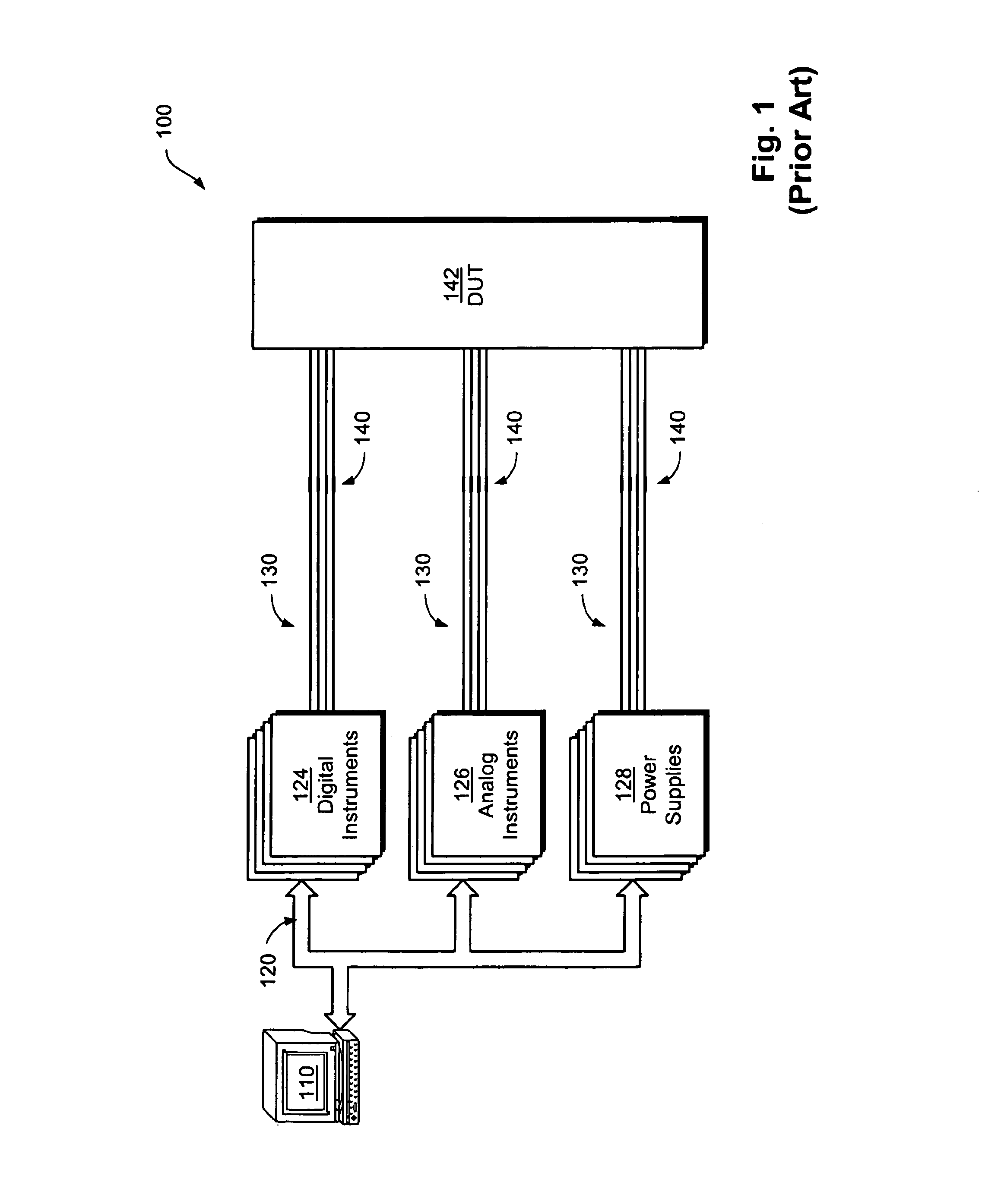
[0019]FIG. 1 is a highly simplified illustration of a conventional architecture 100 for an automatic test system, or “tester,” in which the instant invention can be used. A host computer 110 runs a program for testing a device under test (“DUT”) 142 using a variety of electronic hardware. This hardware generally includes digital instruments 124, analog instruments 126, and power supplies 128.

[0020]The electronic hardware is connected to the DUT 142 via a plurality of lines 130 and respective contacts 140. The contacts 140 generally consist of spring-loaded pins that extend from the tester. The pins can be either single-ended or coaxial. The DUT is placed on a device interface board, or “DIB.” The DIB generally includes conductive pads arranged in patterns that match the patterns of spring-loaded pins extending from the tester. The pins make contact with the pads to form connections between the tester and the DUT 142.

[0021]The digital instruments 124 t...


PUM


Abstract

A system and method for economically yet thoroughly testing serial ports of electronic devices includes a receiver and a transmitter. The receiver is coupled to a TX line of a device under test for receiving an input serial bit stream from the device under test. The transmitter is coupled to a RX line of the device under test for providing an output serial bit stream to the device under test. The receiver is coupled to the transmitter for establishing a loopback connection. A time distortion circuit is interposed between the receiver and the transmitter, for adding predetermined amounts of timing distortion to the output serial bit stream. In addition, a selector is interposed between the receiver and the transmitter, for selecting between the receiver and a direct input. The direct input provides an algorithmic test signal that differs from the input serial bit stream received by the receiver. The direct input thus allows a tester to exercise the device under test with a test signal that differs from the signal that the device under test generates. A time measurement circuit measures timing characteristics of the device under test, and a parametric measurement circuit measures steady-state characteristics of the device under test.

Description

[0001]This invention relates generally to automatic test equipment for electronics, and, more particularly, to the automatic testing of electronic devices that include serial communication ports.BACKGROUND OF THE INVENTION[0002]As electronic devices grow in complexity, greater numbers of leads are required for forming connections between different devices. Consequently, the layout and design of circuit boards has become increasingly complex. Serial communication ports offer a partial remedy to this complexity, as they allow devices to communicate using far fewer lines than parallel devices. Serial ports communicate via only two lines—one for transmitting data and one for receiving data. These lines can be single-ended (i.e., one signal referenced to ground) or differential (i.e., two complementary signals, neither of which is ground). To transfer data at rates comparable to parallel ports, serial ports tend to operate at much higher speeds than parallel ports. Modem serial ports ope...

Claims


Application Information

Patent Timeline
Patent Type & Authority Patents(United States)
IPC IPC(8): G01R31/28G01R31/30G01R31/317G06F11/22H04L1/24H04L25/02
CPCG01R31/3004H04L1/243G01R31/31716G01R31/3016G06F11/00
Inventor PANIS, MICHAEL C.ROBBINS, BRADFORD B.
Owner TERADYNE
Why Eureka
Try Eureka