Suspended gas distribution plate

a gas distribution plate and gas distribution plate technology, applied in the field of gas distribution manifolds, can solve the problems of affecting reducing the service life so as to facilitate the operation of the perforated gas distribution plate, avoid distortion or cracking of the gas distribution plate, and minimize the effect of gas leakag

Inactive Publication Date: 2006-03-28
APPLIED MATERIALS INC
View PDF36 Cites 247 Cited by
  • Summary
  • Abstract
  • Description
  • Claims
  • Application Information

AI Technical Summary

Benefits of technology

[0008]The invention is a gas inlet manifold for a plasma chamber. The manifold has a perforated gas distribution plate suspended by a flexible side wall which accommodates thermal expansion or contraction of the gas distribution plate. The invention is advantageous to avoid distortion or cracking of the gas distribution plate in response to such thermal expansion or contraction.
[0009]The invention is a method of suspending a gas distribution plate from a plurality of side wall segments separated by gaps. One aspect of the invention includes positioning a novel sealing cover that minimizes gas leakage through the gaps while permitting movement of the flexible side wall segments. In another aspect of the invention, each of two adjacent side wall segments has a side portion in which a bend is formed so that the side portions of the two adjacent side wall segments are coplanar.
[0010]In another aspect, the invention is facilitates operation of the perforated gas distribution plate at an elevated temperature. The gas distribution plate is suspended from the chamber wall by inlet manifold side walls. The inlet manifold side walls interpose substantial thermal impedance between the gas distribution plate and the chamber wall, thereby allowing the gas distribution plate to increase in temperature. This aspect of the invention is advantageous to help reduce heat loss from the exposed surface of the workpiece during operation of the chamber.

Problems solved by technology

Rigid mounting has the disadvantage of not accommodating thermal expansion of the perforated plate as it acquires heat from the plasma.
The consequent mechanical stresses on the plate can distort or crack the plate.
Another shortcoming of conventional gas distribution plates is that they generally remain cool during the CVD process, hence they contribute to undesirable heat loss from the surface of the substrate.
Therefore, conventional designs typically maintain the gas distribution plate at an undesirably low temperature.

Method used


Image

  • Suspended gas distribution plate
  • Suspended gas distribution plate
  • Suspended gas distribution plate

Examples


embodiment # 1

Embodiment #1—Back Wall Provides Vacuum Seal

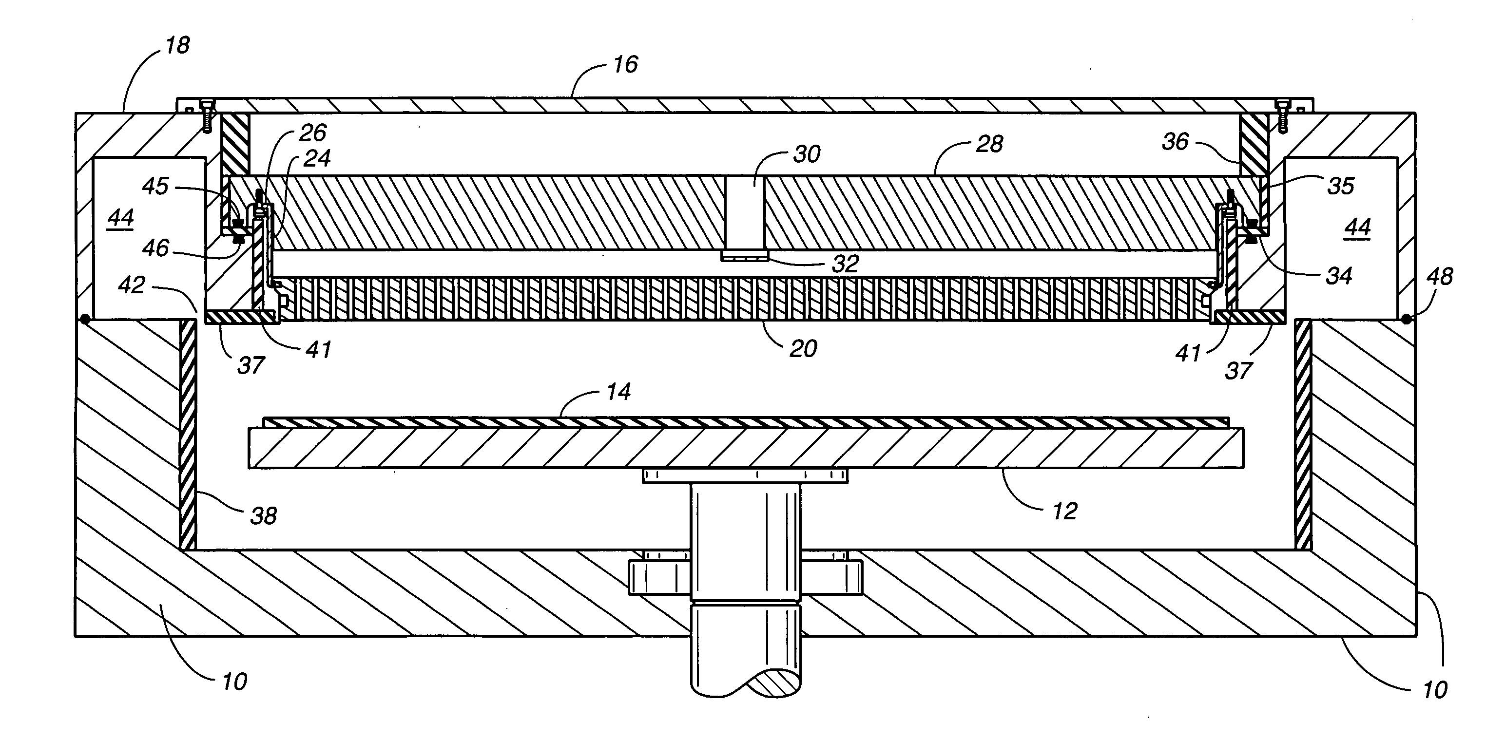
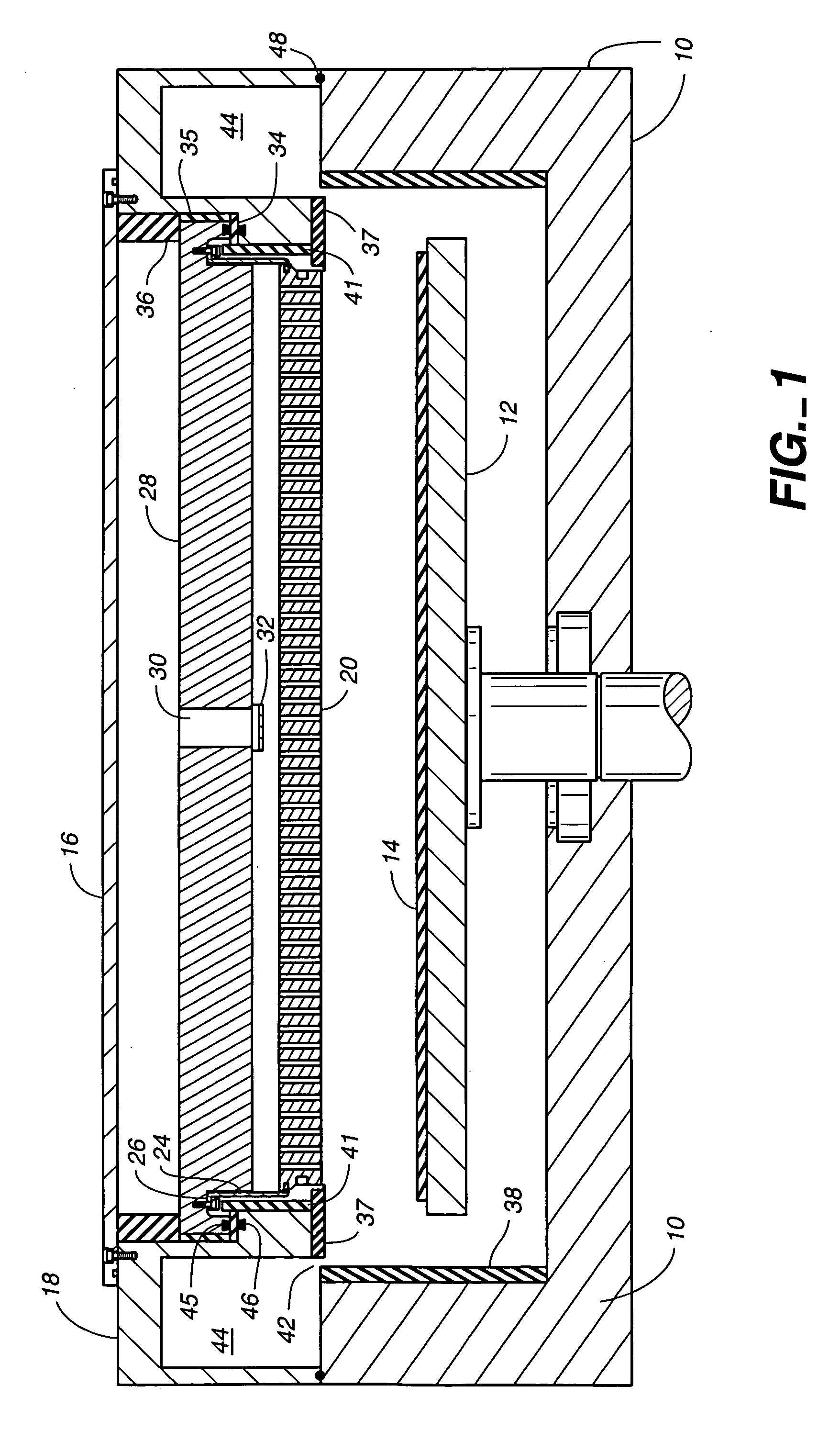
[0041]In the embodiments shown in FIGS. 1–8, the upper surface of the back wall 28 is the only component of the gas inlet manifold that is exposed to the ambient atmospheric pressure, hence the back wall is the only component of the gas inlet manifold that requires a vacuum seal. Specifically, a vacuum seal between the chamber interior and the ambient atmosphere outside the chamber is provided by a first vacuum sealing material 45 between the back wall 28 and the dielectric spacer 34, and by a second vacuum sealing material 46 between the dielectric 34 and a surface of the chamber wall. In the illustrated embodiments, the latter surface is the surface of the lid 18 on which the dielectric rests. Because the illustrated embodiments include a removable lid 18, an additional vacuum sealing material 48 is required between the lid and the chamber side wall 10. Sealing materials 45, 46 and 48 preferably are O-rings.

[0042]In this embodiment, a ga...

embodiment # 2

Embodiment #2—Upper Flange of Side Wall Also Provides Vacuum Seal

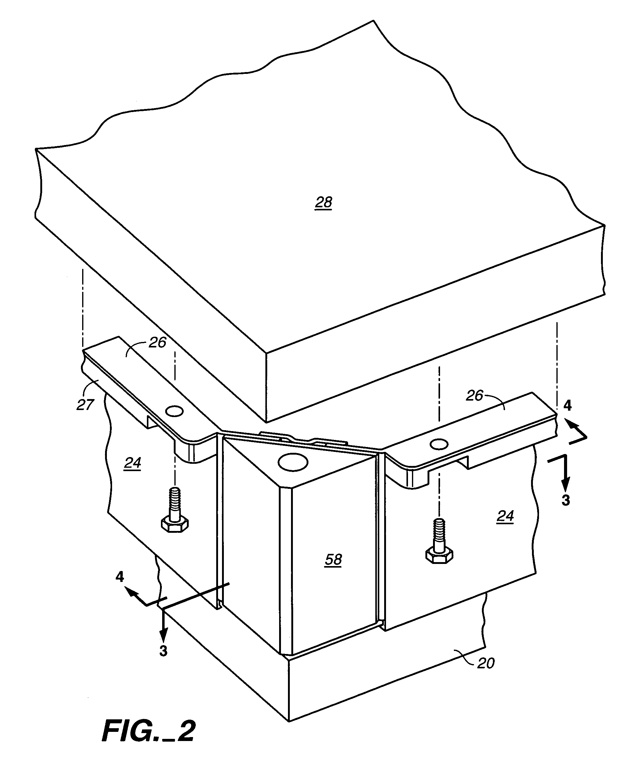
[0044]In an alternative embodiment shown in FIGS. 9–11, the upper flange 70 of the flexible side wall or suspension 24 of the gas inlet manifold is partially exposed to the external ambient atmosphere. This contrasts with the embodiments of FIGS. 1–8 in which the entire suspension 24, including the upper lip 26, is completely enclosed by the perimeter of the back wall 28 of the gas inlet manifold. Consequently, in the embodiment of FIGS. 9–11, the upper flange 70 of the flexible side wall must contribute to the vacuum seal between the chamber interior and the external ambient atmosphere, which requires one more O-ring than the previous embodiments.

[0045]As in the previous embodiments, two O-rings 45, 46 or other sealing material are required on either side of the dielectric spacer 34, i.e., a first O-ring 45 between the dielectric and the upper flange 70 of the flexible side wall 24, and a second O-ring 46 between the ...


PUM

PropertyMeasurementUnit
angleaaaaaaaaaa
angleaaaaaaaaaa
frequencyaaaaaaaaaa

Abstract

A gas inlet manifold for a plasma chamber having a perforated gas distribution plate suspended by flexible side walls. The flexible suspension minimizes mechanical stress due to thermal expansion of the gas distribution plate. In another aspect, the suspension provides thermal isolation between the gas distribution plate and other components of the chamber.

Description

CROSS REFERENCE TO RELATED APPLICATIONS[0001]This patent application is a divisional of application Ser. No. 10 / 293,544 filed Nov. 12, 2002, now U.S. Pat. No. 6,823,589 which is a divisional of Ser. No. 09 / 488,612 filed Jan. 20, 2000, now U.S. Pat. No. 6,477,980 issued Nov. 12, 2002.FIELD OF THE INVENTION[0002]The invention relates generally to gas distribution manifolds for supplying gas to a plasma chamber. More specifically, the invention relates to such a manifold having a perforated gas distribution plate suspended by flexible side walls which accommodate thermal expansion of the plate.BACKGROUND OF THE INVENTION[0003]Electronic devices, such as flat panel displays and integrated circuits, commonly are fabricated by a series of process steps in which layers are deposited on a substrate and the deposited material is etched into desired patterns. The process steps commonly include plasma enhanced chemical vapor deposition (CVD) processes and plasma etch processes.[0004]Plasma pro...

Claims


Application Information

Patent Timeline
Patent Type & Authority Patents(United States)
IPC IPC(8): B23P15/00C23C16/455H01L21/00B01J19/08C23C16/44C23C16/509H01J37/32H01L21/205H01L21/302H01L21/3065H01L21/31
CPCC23C16/455C23C16/45565H01J37/3244C23C16/5096Y10T29/49826Y10T29/49428
Inventor WHITE, JOHN M.KELLER, ERNSTBLONIGAN, WENDELL T.
Owner APPLIED MATERIALS INC
Why Eureka
Try Eureka