
Miniaturized pressure sensor

a technology of pressure sensor and sensor, applied in the direction of fluid pressure measurement by electric/magnetic elements, measuring devices, instruments, etc., can solve problems such as reducing sensitivity

Inactive Publication Date: 2006-03-28
SILEX MICROSYST
View PDF9 Cites 34 Cited by
  • Summary
  • Abstract
  • Description
  • Claims
  • Application Information

AI Technical Summary

Benefits of technology

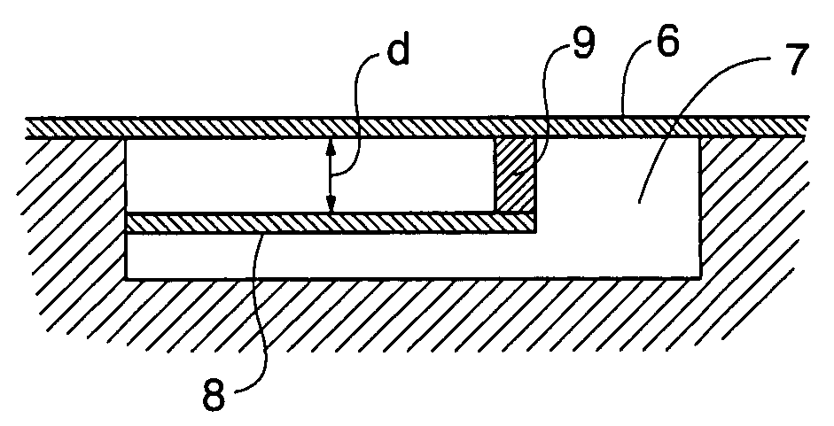
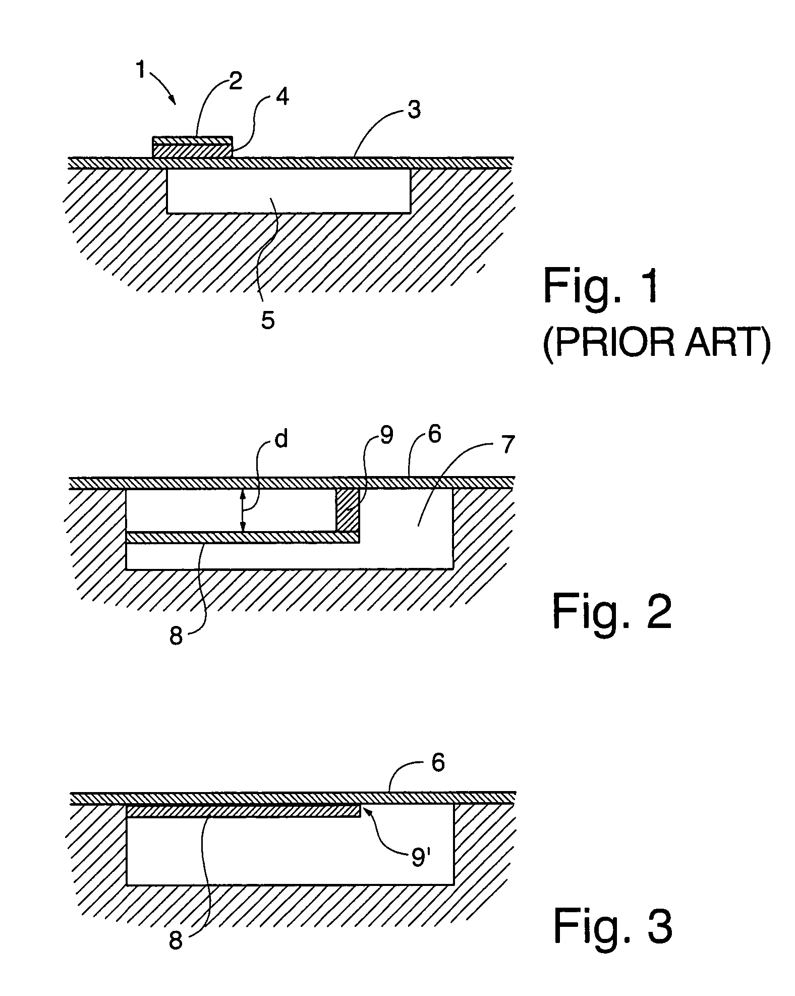
[0005]Thus, in view of the restricted sensitivity of the above discussed prior art sensor, the inventors have sought to develop an improved sensor. This has now been achieved by a sensor comprising a vacuum cavity sealed by a diaphragm, in which a leverage of the deflection of the diaphragm caused by the pressure exerted thereon, is achieved by suspending a force transducing beam in the diaphragm inside the vacuum cavity. The leverage brings about an amplification of the signal from the strain gauge on said beam.
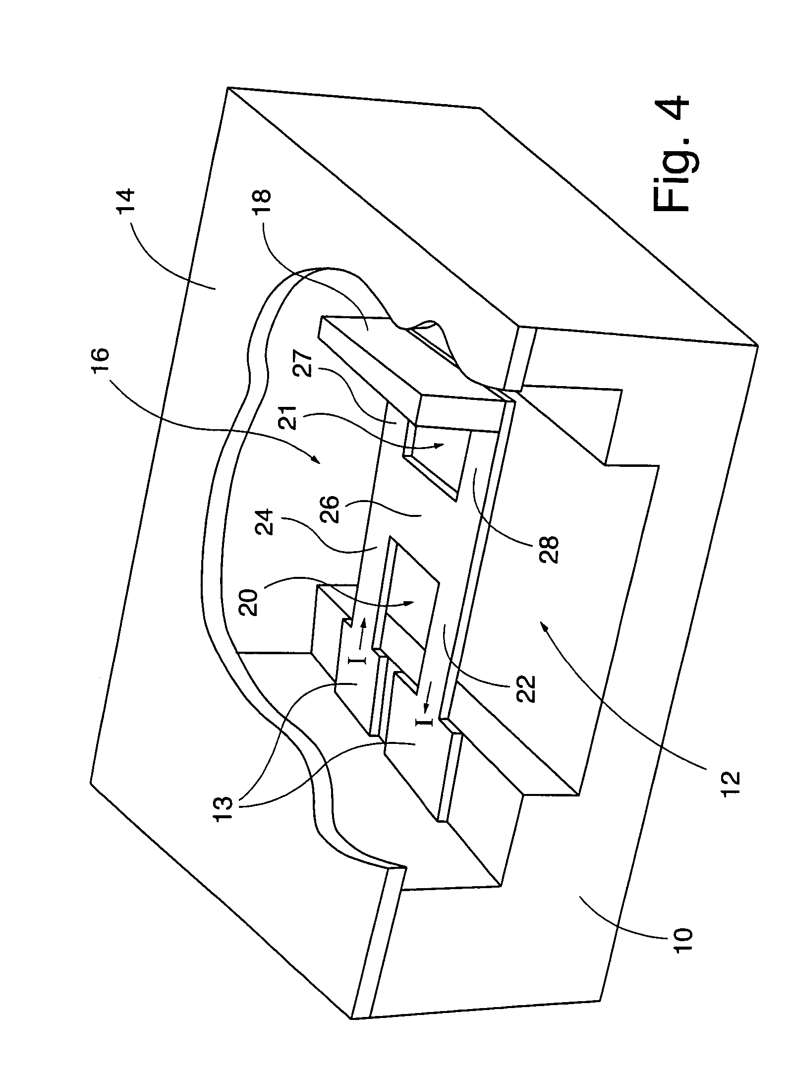
[0006]The deflection is sensed in one embodiment by a H-shaped free-hanging strain-gauge which is located beneath, and fully enclosed by, the diaphragm, inside the reference vacuum cavity. This enables a leverage effect without the need for an insulation layer, which would introduce unwanted stiffening. The strain-gauge is thin and only supported at the beam ends (reffered to by the expression “free-hanging”) to further reduce stiffening effects and thereby increasing the pressure sensitivity.

Problems solved by technology

However, the thickness of such an insulator also stiffens the diaphragm, thus reducing the sensitivity.

Method used


Image

  • Miniaturized pressure sensor
  • Miniaturized pressure sensor
  • Miniaturized pressure sensor

Examples


Embodiment Construction

[0023]FIG. 1 shows a prior art piezo resistive pressure sensor 1, where the strain gauge 2 comprising a piezo resistive element is provided on top of the diaphragm 3 with an insulating layer 4 disposed therebetween. The diaphragm covers a reference vacuum cavity 5. As already indicated above, this insulation layer, although increasing the sensitivity to some degree, also causes a stiffening of the diaphragm, which counteracts the effect of the insulation layer.

[0024]In FIG. 2 a sensor according to the invention is schematically illustrated in cross section. It comprises a diaphragm 6 covering a reference vacuum cavity 7. Within the cavity 7 and suspended by the diaphragm 6 by means of a finite suspension member 9 at one end, a force transducing beam 8 is provided. The beam 8 is attached at its other end inside the cavity such that there will be a finite distance between the diaphragm and the beam. However, it is also possible to make the diaphragm 6 and beam 8 so as to be located in...


PUM


Abstract

An entirely surface micromachined free hanging strain-gauge pressure sensor is disclosed. The sensing element consists of a 80 μm long H-shaped double ended supported force transducing beam (16). The beam is located beneath and at one end attached to a square polysilicon diaphragm (14) and at the other end to the cavity edge. The sensor according to the invention enables a combination of high pressure sensitivity and miniature chip size as well as good environmental isolation. The pressure sensitivity for the sensor with a H-shaped force transducing beam, 0.4 μm thick was found to be 5 μV / V / mmHg.

Description

[0001]The present invention relates to miniaturized pressure sensors. More specifically it relates to such a sensor wherein the sensitivity has been substantially improved by providing a force transducing beam inside a vacuum cavity. The sensitivity is improved by the mechanical leverage effect obtained by making the beam suspended by a diaphragm in one end point. In a preferred embodiment it relates to a pressure sensor employing a strain gauge as the pressure transducing element.BACKGROUND OF THE INVENTION[0002]Blood pressure measurement in the coronary artery is most commonly performed using a fluid filled catheter that transfers the pressure to a external pressure sensor or by a catheter based pressure sensor inside the artery. By measuring the pressure with a miniature sensor inside the artery the time response as well as the accuracy can be improved. The miniature sensor based measurement is well suited for use in balloon angioplasty procedures.[0003]Pressure sensors intended ...

Claims


Application Information

Patent Timeline
IPC IPC(8): G01L9/04G01L9/00G01L9/06
CPCG01L9/0042G01L9/0083G01L9/006
Inventor KAELVESTEN EDVARDMELV DOT OVER AS PATRIKSTEMME GOERAN
Owner SILEX MICROSYST
Learn More