Device and method for measuring element temperature of air-fuel ratio sensor, and device and method for controlling heater of air-fuel ratio sensor

a technology of air-fuel ratio and element temperature, which is applied in the direction of electric control, instruments, machines/engines, etc., can solve the problems of increasing the power consumption of the heater, deteriorating the estimation accuracy affecting the accuracy of the measurement of the element temperature, so as to prevent the fluctuation of the sensor element, accurately compute, and measure accurately

Inactive Publication Date: 2006-03-28
HITACHI LTD
View PDF33 Cites 13 Cited by
  • Summary
  • Abstract
  • Description
  • Claims
  • Application Information

AI Technical Summary

Benefits of technology

[0010]Another object of the present invention is to enable an accurate judgment of the activation status of the air-fuel ratio sensor based on the accurately measured element temperature.
[0011]Yet another object of the present invention is to control a sensor element to the desired element temperature by controlling a heater for heating the sensor element based on the accurately measured element temperature.
[0012]Still another object of the present invention is to improve the accuracy of an air-fuel ratio feedback control based on the above heater control.
[0016]With this constitution, since there can be considered an influence of voltage output for air-fuel ratio detection of the air-fuel ratio sensor by the sensor output just before applied with the voltage, the estimation accuracy of the sensor element temperature is improved, thereby enabling an accurate activation judgment and the like of the air-fuel ratio sensor.
[0019]Thereby, it becomes possible to prevent the fluctuation of sensor element temperature (in other words, the fluctuation of internal resistance of the sensor element), which is caused by the fluctuation of heater application voltage accompanying the control of the heater for heating the sensor element, so that the internal resistance of the sensor element can be measured accurately, and the element temperature can be accurately computed based on the measured internal resistance.
[0020]Further, it becomes possible to feedback control the heater for heating the sensor element, based on the accurately detected element temperature, so that the element temperature reaches a target temperature, thereby enabling the sensor element to be controlled to the desired temperature.

Problems solved by technology

Therefore, if the sensor output is used as it is for measurement of internal resistance, an estimation error of the element temperature becomes too large.
This causes an error in the measurement of internal resistance, to lead to the deterioration of estimation accuracy of the element temperature.
Such deterioration of estimation accuracy of the element temperature not only causes the deterioration of the ability to control the element to the target temperature when controlling the power supply to the heater for heating the sensor element, but also causes the increase of the power consumption by the heater.
It further causes a bad influence to the feedback control of the air-fuel ratio.

Method used


Image

  • Device and method for measuring element temperature of air-fuel ratio sensor, and device and method for controlling heater of air-fuel ratio sensor
  • Device and method for measuring element temperature of air-fuel ratio sensor, and device and method for controlling heater of air-fuel ratio sensor
  • Device and method for measuring element temperature of air-fuel ratio sensor, and device and method for controlling heater of air-fuel ratio sensor

Examples


first embodiment

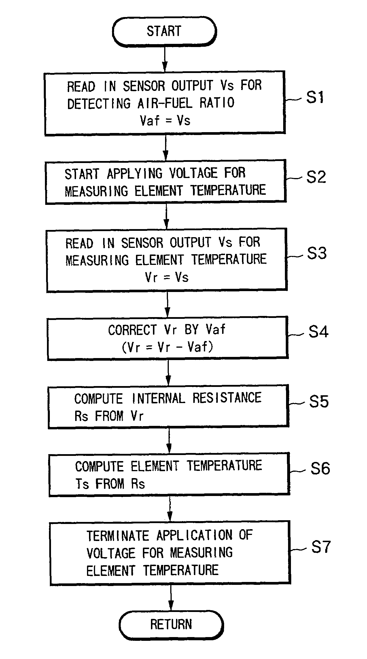
[0061]FIG. 5 is a flowchart showing the routine for measuring the element temperature to be executed at a predetermined crank angle cycle.

[0062]In step 1 (abbreviated as “S1” in the drawing, the same holds hereinafter), the sensor output Vs is read in and set to Vaf=Vs, based on which the air-fuel ratio λ is detected.

[0063]In step 2, the switching element 13 is turned ON, and the application of voltage Vcc for measuring the element temperature to the sensor element 20 is started. In other words, immediately after reading the sensor output for air-fuel ratio detection, the application of voltage Vcc for measuring the element temperature is started.

[0064]In step 3, after a first predetermined time T1 has passed from the starting of application of voltage for measuring the element temperature, the sensor output Vs is read in and set to Vr=Vs so as to measure the internal resistance of the sensor element 20.

[0065]In step 4, the sensor output Vr being applied with voltage is corrected b...

second embodiment

[0082]FIG. 8 is a flowchart of the element temperature measurement routine to be executed instead of the flowchart of FIG. 5.

[0083]Steps 51 through 53 are the same as steps 1 through 3 in the flowchart of FIG. 5.

[0084]In step 54, the internal resistance Rs of the sensor element 11 is computed based on the sensor output Vr being applied with voltage without correction.

[0085]In step 55, the correction value for the internal resistance Rs (Rs correction value) is computed from the sensor output Vaf just before applied with voltage.

[0086]In step 56, the internal resistance Rs computed in step 54 is corrected by the Rs correction value computed in step 55.

[0087]The correction here is performed so that when the sensor output Vaf just before applied with voltage is greater, the internal resistance Rs is corrected to a smaller value, since when the sensor output Vaf just before applied with voltage is greater, the internal resistance Rs is computed to be greater than the actual value.

[0088...

third embodiment

[0089]FIG. 9 is a flowchart showing the element temperature measurement routine to be executed instead of the flowchart of FIG. 5.

[0090]Steps 61 through 63 are the same as steps 1 through 3 in the flowchart of FIG. 5.

[0091]In step 64, the internal resistance Rs of the sensor element 20 is computed based on the sensor output Vr being applied with voltage without correction. In step 65, the element temperature Ts is computed based on the internal resistance Rs of the sensor element 20 by referring to a table and the like.

[0092]In step 66, the correction value for element temperature Ts (Ts correction value) is computed based on the sensor output Vaf just before applied with voltage.

[0093]In step 67, the element temperature Ts computed in step 64 is corrected by the Ts correction value computed in step 66.

[0094]The correction here is performed so that when the sensor output Vaf just before applied with voltage is greater, the internal resistance Rs is corrected to a smaller value, sin...


PUM

PropertyMeasurementUnit
temperatureaaaaaaaaaa
internal resistanceaaaaaaaaaa
voltageaaaaaaaaaa

Abstract

A device according to the present invention is provided with element temperature measurement voltage application circuit for temporarily applying a predetermined voltage for element temperature measurement to a sensor element of an air-fuel ratio sensor equipped to an exhaust system of an internal combustion engine, first sensor output reading circuit for reading in a sensor output just before applied with the voltage, and second sensor output reading circuit for reading in a sensor output being applied with the voltage, wherein the element temperature of the air-fuel ratio sensor is estimated based on the sensor output just before applied with the voltage and the sensor output being applied with the voltage. Further, during internal resistance measurement of the sensor element of the air-fuel ratio sensor equipped to the exhaust system of the internal combustion engine, a voltage applied to the heater for heating the sensor element is maintained to be constant.

Description

[0001]This application is a divisional of application Ser. No. 09 / 853,872 filed May 14, 2001 now U.S. Pat. No. 6,712,054.FIELD OF THE INVENTION[0002]The present invention relates to a technique for measuring the element temperature of an air-fuel ratio sensor (including an oxygen sensor) equipped to an exhaust system of an internal combustion engine and utilized for controlling an air-fuel ratio of the engine, and to a technique for controlling a heater for heating a sensor element equipped to the air-fuel ratio sensor based on the measured element temperature.DESCRIPTION OF THE RELATED ART[0003]Heretofore, there has been known an air-fuel ratio control device of an internal combustion engine for detecting an actual air-fuel ratio of the engine based on the oxygen concentration and the like in the exhaust using an air-fuel ratio sensor, and performing a feedback control of fuel supply quantity to the engine so that the actual air-fuel ratio reaches a target air-fuel ratio.[0004]In o...

Claims


Application Information

Patent Timeline
Patent Type & Authority Patents(United States)
IPC IPC(8): F02D45/00F02D41/14G01N27/406
CPCG01N27/4067F02D41/1494
Inventor HOSOYA, HAJIMETAKAHASHI, KOJIOHKUMA, SHIGEO
Owner HITACHI LTD
Why Eureka
Try Eureka