Coil bobbin structure

Inactive Publication Date: 2006-03-28
MINEBEA CO LTD
View PDF10 Cites 5 Cited by
  • Summary
  • Abstract
  • Description
  • Claims
  • Application Information

AI Technical Summary

Benefits of technology

[0012]The problems enumerated so far provided the impetus for the present invention, and its object lies in providing a coil bobbin structure that allows intersection of the wire to be avoided with a simple structure and improvement of reliability to be devised, at the same time allows the possible use of automatic winding machines.
[0014]Therefore, according to the invention, since each extremity of the wire is wound into each respectively independent terminal support, guided along the guide groove to each terminal pin, then wound and fixed to each terminal pin, crossing over of the wire can be avoided with a simple structure, improved of reliability can be obtained by avoiding insulation deterioration and short circuit At the same time, the use of automatic winding machines becomes
[0016]In this embodiment, the length of winding to each terminal support of each extremity of the wire can be sufficiently secured, and the extremities of the wire can be reliably fixed to the terminal pins.

Problems solved by technology

However, there was the problem that when the extremity portions of the winding start and the winding ends of the wire 209 intersect as described above, the wire 209 contacts with itself at the intersection, and due to oscillations, shocks and the like, the coat at the contact portion of the wire 209 wears off, or scratches occur on wire 209, inducing deterioration of the insulating withstand voltage or short circuit.
However, with the above-mentioned structure, since the shape of the coil bobbin 301 is complicated, there is the problem that automatic winding of wire 309 by automatic winding machines becomes difficult.

Method used


Image

  • Coil bobbin structure
  • Coil bobbin structure
  • Coil bobbin structure

Examples


Embodiment Construction

[0030]In the following, configurations of the present invention will be explained based on the attached FIGS.

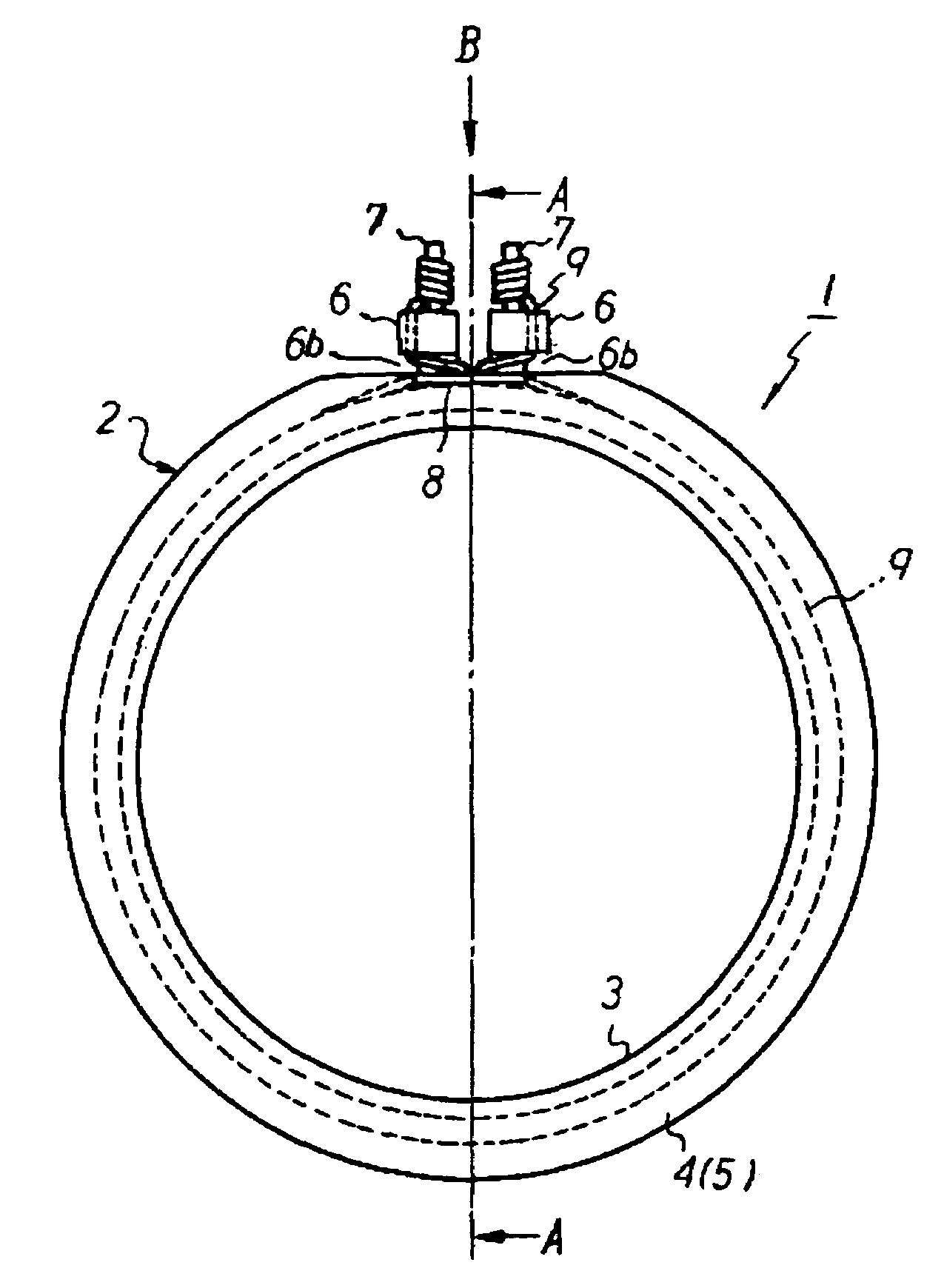
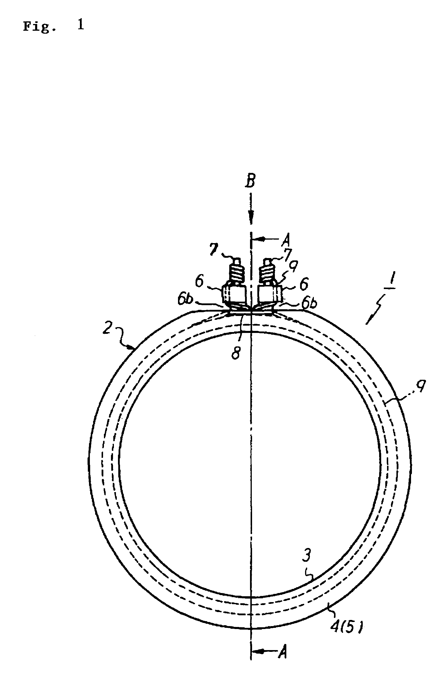
[0031]FIG. 1 is a front view of a coil bobbin equipped with the structure of the present invention, FIG. 2 is a cross sectional view along the A—A line of FIG. 1, FIG. 3 is a view in the direction of arrow B of FIG. 1, FIG. 4 is a partial perspective view in the direction of arrow C of FIG. 3, FIG. 5 is a partial perspective view in the direction of arrow D of FIG. 3.

[0032]In the coil bobbin 1 shown in the FIGS., numeral 2 is a pulley shaped bobbin main body integrally molded in resin (for example nylon 46), and the bobbin main body 2 is formed by ring shaped flanges 4 and 5 having larger diameters than the winding drum portion 3, integrally formed at both ends in the axial direction of the cylindrical winding drum portion 3. Then, at the upper end of one of the flanges 4 of this bobbin main body 2, 2 terminal supports 6, left and right, are provided as a single piece so as t...


PUM


Abstract

To provide a coil bobbin structure that allows intersection of the wire to be avoided with a simple structure and improved reliability to be attained, while at the same time, allowing the possible use of automatic winding machines. In a coil bobbin 1 consisting of a bobbin main body 2 constituted by forming flanges 4 an 5 at both ends in the axial direction of a cylindrical winding drum portion 3, wherein at a portion of one of the flanges 4, a terminal support 6 is provided protruding in the outer direction of the diameter direction, said terminal support 6 being provided with 2 terminal pins 7 that are standing, at the same time, both ends of a magnet wire 9 that is wound around the outer circumference of the winding drum portion 3 of the bobbin main body 2, are respectively wound and fixed to the terminal pins 7, 2 terminal supports 6 are installed and the terminal pins 7 are provided respectively to each terminal support 6 so as to be standing, at the same time, a guide groove 6a is provided respectively to each terminal support 6, each extremity of the magnet wire 9 passes from the winding drum portion 3 through the gap between both terminal supports 6, is wound into each terminal support 6, passed through the guide groove 6a, is guided to the terminal pin 7 and is wound and fixed to said terminal pin 7.

Description

CROSS-REFERENCE TO RELATED APPLICATIONS[0001]This application claims priority from Japanese Patent Application No. 2002-345761 filed on Nov. 28, 2002.BACKGROUND OF THE INVENTION[0002]1. Field of the Invention[0003]The present invention relates to the structure of a coil bobbin used in rotary transformers and the like such as various motors and resolvers.[0004]2. Description of the Related Art[0005]As shown in FIG. 6, a coil bobbin 101 used in rotary transformers and the like such as various motors and resolvers, is constituted by forming flanges 104 and 105 at both ends in the axial direction of a cylindrical winding drum portion 103 of a bobbin main body 102, wherein at a portion of one of the flanges 104, a terminal support 106 is provided as a single piece protruding in the outer direction of the diameter direction, the terminal support 106 being provided with 2 terminal pins 107 that are standing, at the same time, both ends of a wire 109 that is wound around the outer circumfer...

Claims


Application Information

Patent Timeline
IPC IPC(8): B21F3/04H01F5/04H01F5/02H01F41/06H01F41/10
CPCH01F5/04H01F41/10H01F41/0666H01F41/076
Inventor MATSUURA, MUTSUMIYOSHII, GENTA
Owner MINEBEA CO LTD
Why Eureka
Try Eureka