Gear drive with integrated torque limiting coupling

Inactive Publication Date: 2006-03-28
GKN WALTERSCHEID GETRIEBE
View PDF23 Cites 4 Cited by
  • Summary
  • Abstract
  • Description
  • Claims
  • Application Information

AI Technical Summary

Benefits of technology

[0021]To improve lubrication of the locking member coupling, the connecting shaft includes a bore. The bore starts from an end face, for lubricating purposes, leads to the locking members of the locking member coupling. To avoid increased wear, the locking member coupling is lubricated from the inside through the bore in the connecting shaft. Furthermore, through this arrangement

Problems solved by technology

A disadvantage of these embodiments is that the input shaft of the gear drive freely projects in the region of the torque limiting coupling.
In addition, the torque limiting coupling

Method used


Image

  • Gear drive with integrated torque limiting coupling
  • Gear drive with integrated torque limiting coupling
  • Gear drive with integrated torque limiting coupling

Examples


Embodiment Construction

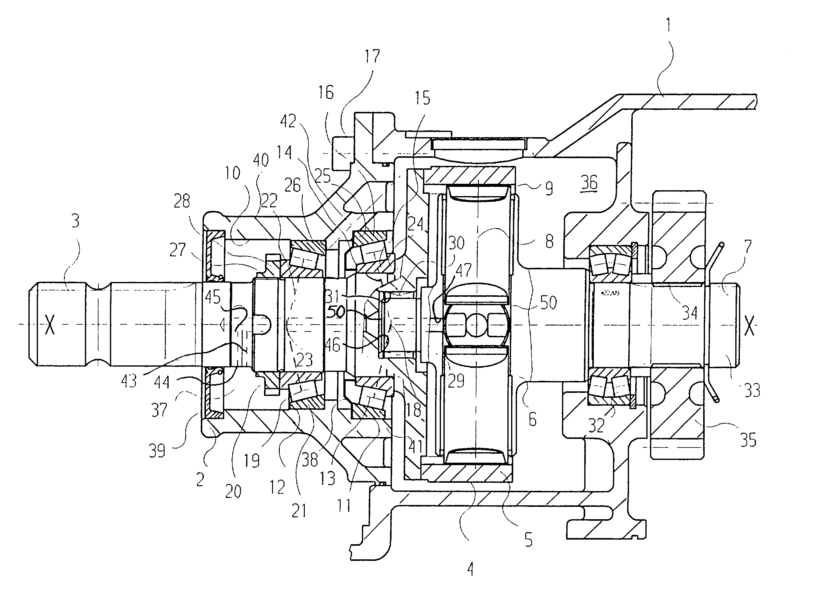
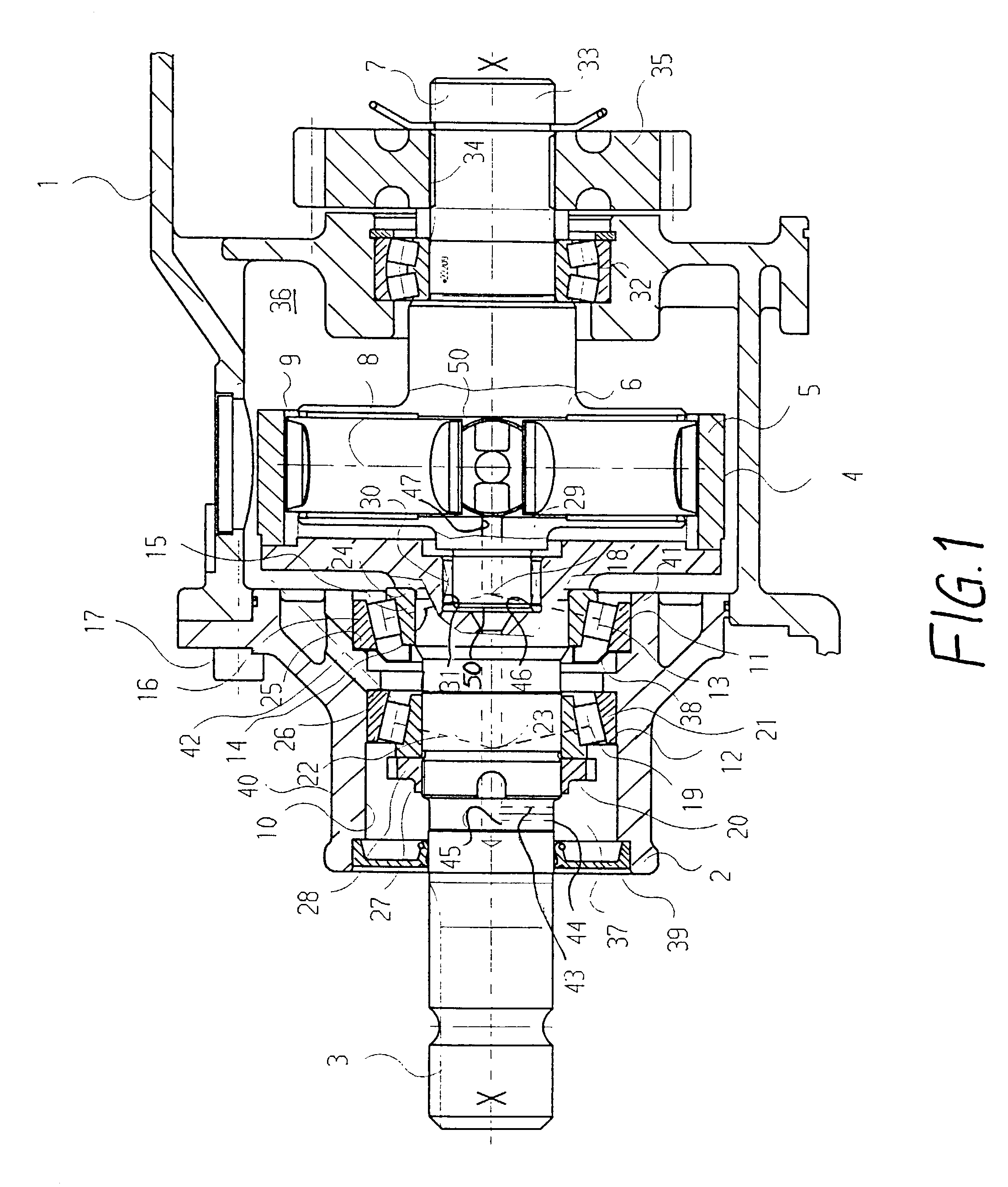
[0025]FIG. 1 illustrates a gear drive with a drive body 1 and a drive cover 2. Together, the drive body 1 and drive cover form a drive housing. A driveshaft 3 is supported in the drive cover 2. The driveshaft 3 is rotatable around an axis of rotation X—X. The driveshaft 3, with respect to drive, is connected to a torque limiting coupling 4. For this purpose, the driveshaft 3 is welded to an outer part 5 of the torque limiting coupling 4. The torque limiting coupling includes an inner part 6. The inner part 6 integrally changes into a connecting shaft 7. The torque limiting coupling 4 is provided in the form of a ratchet clutch. The connecting shaft 7 is rotatably arranged inside the drive body 1 around the axis of rotation X—X.

[0026]Locking members 8 are radially displaceably arranged in the inner part 6. The locking members 8 engage grooves 9 of the outer part 5. This ensures a rotationally fast connection between the inner part 6 and the outer part 5. When a certain torque value i...


PUM


Abstract

A gear drive has a drive housing (1, 2) with a driveshaft (3) exiting the drive housing (1, 2) through a bore (10). The driveshaft 13 is rotatably supported in the drive housing (1, 2) around an axis of rotation X—X. A connecting shaft (7) is arranged inside the drive housing (1, 2). The connecting shaft (7) is connected in a rotationally fast way to a drive gear (35). A torque limiting coupling (4) is arranged inside the drive housing (1, 2). The input end of the torque limiting coupling (4) is connected to the driveshaft (3). The output end of the torque limiting coupling (4) is connected to the connecting shaft (7). The driveshaft (3) and the connecting shaft (7) are supported relative to one another by a radial bearing (30). The gear drive ensures that the driveshaft (3) and the connecting shaft (7) can more easily accommodate bending moments and transverse forces.

Description

CROSS-REFERENCE TO RELATED APPLICATION[0001]This application claims priority to German Patent Application No. 10120758.1 filed Apr. 27, 2001, which application is herein expressly incorporated by reference.BACKGROUND AND SUMMARY OF THE INVENTION[0002]The invention relates to a gear drive with a torque limiting coupling to protect drive-lines in machinery, especially agricultural implements or machinery. Torque limiting couplings arranged at input shafts, which lead to gear drives, are known. Splines are used to connect the input shaft of the gear drive to the overload coupling.[0003]DE 41 37 829 C2 illustrates a torque limiting coupling with an outer part and an inner part. The inner part has an axially extending slip-on bore with splines. The coupling can be slipped onto corresponding splines of a drive input shaft.[0004]DE 32 05 513 C1 illustrates a torque limiting coupling with an outer part and an inner part. The inner part changes into a hub portion. The hub portion includes a ...

Claims


Application Information

Patent Timeline
IPC IPC(8): F16D7/00F16D41/06F16D43/202F16H35/10F16H57/00F16H57/02
CPCF16D43/2028F16H57/021F16H35/10F16H57/0037
Inventor RAUSCHENBACH, STEFANROTH, ANDREASJACOB, JOHANNESMULLER, SILKE
Owner GKN WALTERSCHEID GETRIEBE
Why Eureka
Try Eureka