Self-servo-writing multi-slot timing pattern

a timing pattern and self-servo-writing technology, applied in the direction of digital recording, maintaining head carrier alignment, instruments, etc., can solve the problems of reducing the amplitude of the signal, increasing the difficulty of such servo-writers in invading the internal environment of the hda for servo, and insufficient traditional servo-writing methods, so as to improve the overall precision of timing propagation, improve the accuracy of timing mark placement, and improve the effect of self-

Inactive Publication Date: 2006-03-28
HITACHI GLOBAL STORAGE TECH NETHERLANDS BV
View PDF9 Cites 12 Cited by
  • Summary
  • Abstract
  • Description
  • Claims
  • Application Information

AI Technical Summary

Benefits of technology

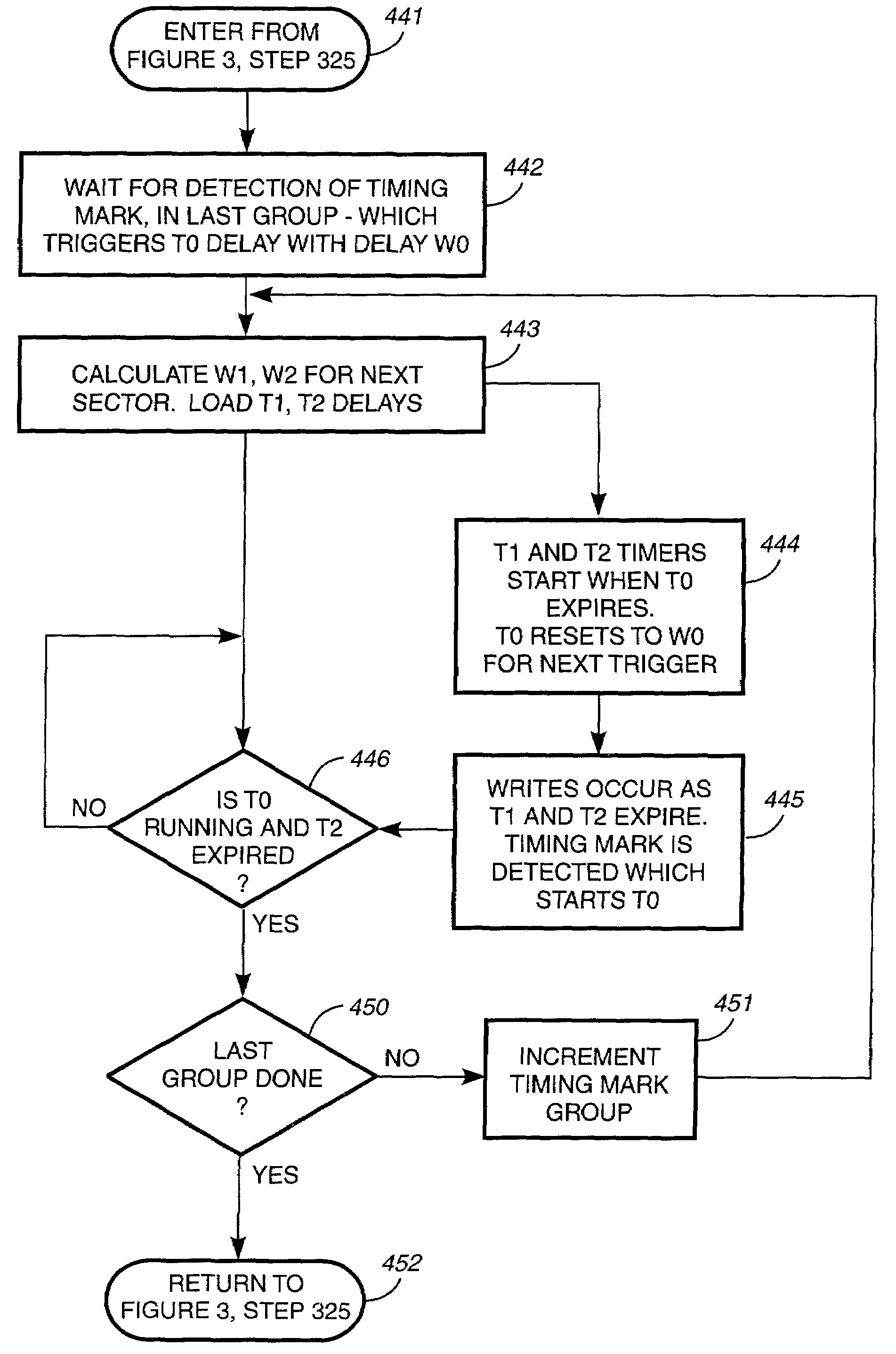
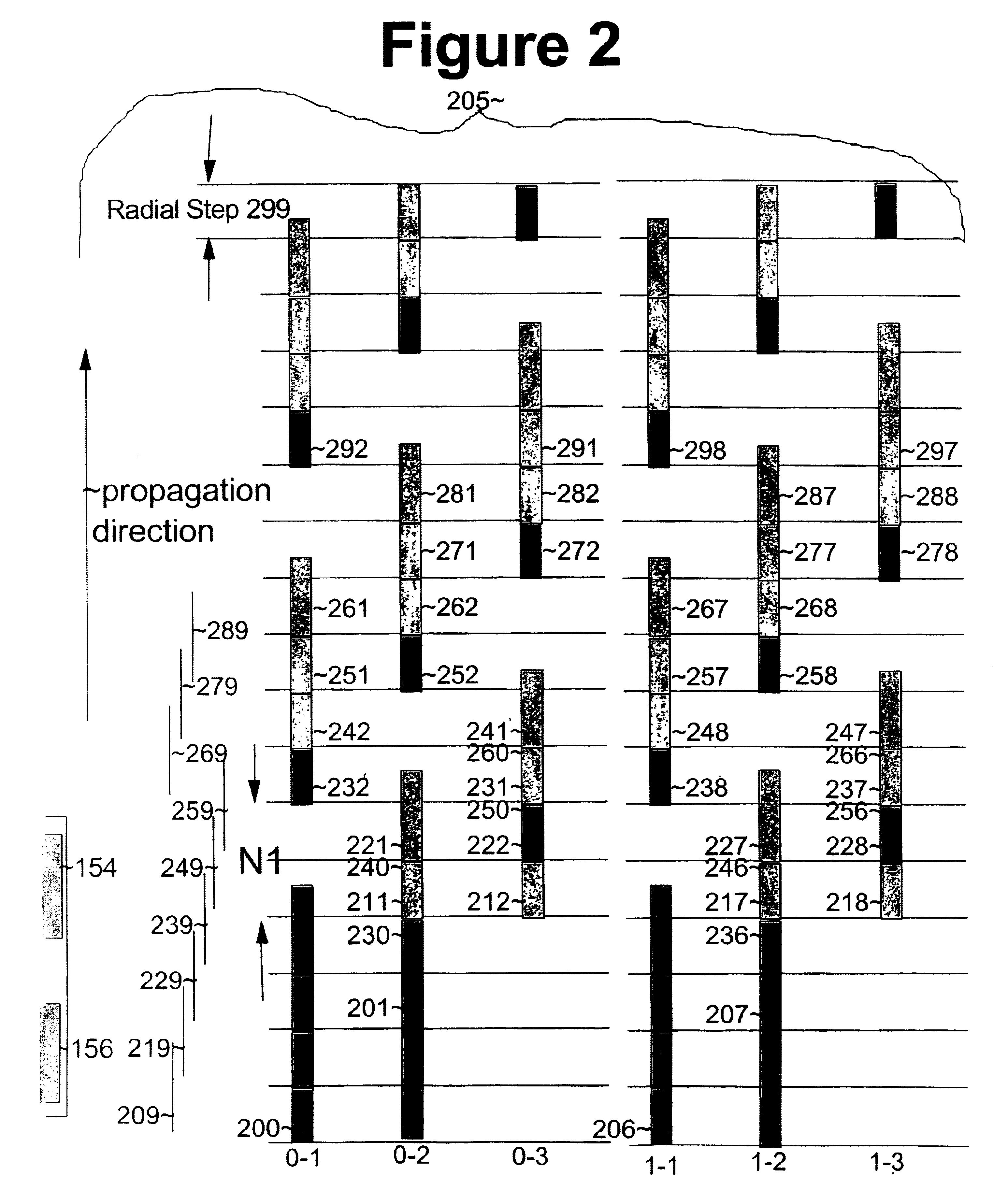
[0025]Briefly, in accordance with the present invention, disclosed is a system and method for improved self-servo-writing of multi-slot timing patterns. Individual timing marks are replaced with groups of timing mark slots. At each timing mark location, a time measurement is made by detecting a timing mark in one of the slots. Timing marks are written in other slots. The combination of timing measurements at every group and timing marks written at every group improves the overall precision of the timing propagation. The improved accuracy of timing mark placement produces a commensurate improvement in the placement of the concomitantly written servo-data. In addition, the alignment accuracy of the written pattern is less sensitive to variations in rotation speed and variations in the shape of written transitions. Moreover, only a single disk revolution is required at each servo radius to write servo data and propagate the timing marks to maintain timing alignment.

Problems solved by technology

Unfortunately, it is becoming more and more difficult for such servo-writers to invade the internal environment of a HDA for servo-writing because the HDAs themselves depend on their covers and castings being in place for proper operation.
Also, some HDAs are very small, less than 2 inches square At such levels of microminiaturization, traditional servo-writing methods are inadequate.
Such interference can reduce the amplitude of the signal and cause data errors.
When such a station is used to perform the servo-writing, manufacturing expenses increase because each disk drive must be mounted in the servo-writer.
When the above self-servo-writing processes are used for drives in which the read and write elements do not overlap, accurate circumferential alignment of the servo-data tracks is not maintained and there is a lack of stability against the growth of random errors in the pattern generation process.
This, unfortunately, can result in odd-even sector asymmetry, reduced signal strength at the timing mark, and increases the overall time between measurements during which the motor speed can significantly vary possibly introducing additional timing errors into measurements of timing mark locations.
This reduces the overall process time.
This constraint limits the types of recording head and timing mark patterns that can be used with the higher accuracy method where every timing mark is both read and written in the same revolution.

Method used


Image

  • Self-servo-writing multi-slot timing pattern
  • Self-servo-writing multi-slot timing pattern
  • Self-servo-writing multi-slot timing pattern

Examples


first embodiment

[0087]The '740 application teaches two embodiments with different delays for writing . The first embodiment is equivalent to the embodiment of the current invention called WWR. In this embodiment, the delay for writing is either the estimated or measured interval between the timing mark from which a delay is measured and the timing mark at the circumferential position to be written, plus the systematic and random error corrections:

delay=interval+systematic+random_error.

second embodiment

[0088]The second embodiment is equivalent to the embodiment of the current invention called DWWR. In this embodiment, the delay for writing is the sum of systematic and random error corrections:

delay=systematic+random_error.

[0089]The '740 application then teaches how to calculate delays for writing from (estimated) intervals. We will use the variable D to represent the sum of the systematic plus random_error terms as defined in the '740 application We will use the variable A to represent any corrections to the interval for variations in the rotation speed, following the methods of prior art. Finally we will describe how to use those delays in the WWR and DWWR embodiments for writing for the case of timing mark groups.

[0090]Calculations of Delays for Writing (WWR Embodiment)

[0091]FIG. 5 is a table of formulae for the write timing slots, read timing slots following incrementing, and write delays for different read slot cases, in one embodiment of the present invention. FIG. 5 summariz...


PUM

PropertyMeasurementUnit
radiusaaaaaaaaaa
of timeaaaaaaaaaa
widthaaaaaaaaaa

Abstract

A system and method for self-servo-writing of multi-slot timing patterns is described. Individual timing marks are replaced with groups of timing mark slots. At each timing mark location, a time measurement is made by detecting a timing mark in one of the slots. Also, extensions to the existing timing marks are written in other slots. The combination of timing measurements at every timing mark and extensions to those timing marks written at every opportunity improves the overall precision of the timing propagation. The improved accuracy of timing mark placement produces a commensurate improvement in the placement of the concomitantly written servo-data. In addition, the alignment accuracy of the written pattern is less sensitive to variations in rotation speed and variations in the shape of written transitions. Moreover, only a single disk revolution is required at each servo radius to write servo data and propagate the timing marks.

Description

BACKGROUND OF THE INVENTION[0001]1. Field of the Invention[0002]The present invention relates to the field of timing pattern generation for self-servo-writing magnetic drives.[0003]2. Description of Related Art[0004]High track densities in rotating media mass storage devices are becoming possible with newer drive technologies. These new technologies include voice-coil and other types of servo positioners as well as the ability to read and write narrower tracks by using, for example, magneto-resistive (MR) head technology. Higher track densities increase the accuracy requirements of servowriting methods for embedded servo systems needed to position the head.[0005]Conventional disk drive manufacturing techniques, for example, include writing servo-tracks on the media of a head disk assembly (HDA) with a specialized servo-writer instrument. Laser positioning feedback is used in such instruments to read the actual physical position of a recording head used to write the servo-tracks. Unf...

Claims


Application Information

Patent Timeline
Patent Type & Authority Patents(United States)
IPC IPC(8): G11B5/09G11B5/596G11B21/10
CPCG11B5/59633G11B5/59605
Inventor CHAINER, TIMOTHY J.SCHULTZ, MARK D.WEBB, BUCKNELL C.
Owner HITACHI GLOBAL STORAGE TECH NETHERLANDS BV
Why Eureka
Try Eureka