Power module and power module with heat sink

a power module and heat sink technology, applied in the field of power modules, can solve the problems of shortened heat cycle longevity of the power module b>1/b>, difficult to absorb stress, and hardening of the proportion to which the stress is applied, and achieve the effect of improving the heat discharge characteristics of the power modul

Inactive Publication Date: 2006-03-28
MITSUBISHI MATERIALS CORP
View PDF24 Cites 28 Cited by
  • Summary
  • Abstract
  • Description
  • Claims
  • Application Information

AI Technical Summary

Benefits of technology

[0009]It is an object of the present invention to provide a power module and power module with an attached heat sink in which an insulated circuit board is brazed directly to a heat discharge plate without any marked warping being generated so as to thereby improve the heat discharge characteristics thereof.

Problems solved by technology

However, if the insulated circuit board 3 is fixed directly to the heat discharge plate 2, then as a result of the temperature of the insulated circuit board 3 repeatedly changing from a high temperature to a low temperature and vice versa by the heat generation and non-heat generation of the semiconductor chip 4 or the like, the drawback occurs that, as a result of stress being repeatedly applied to the first Al plate 3b forming the insulated circuit board 3, the portion to which the stress is applied becomes work-hardened.
Moreover, if the first Al plate 3b becomes work-hardened, then it becomes difficult for the stress to be absorbed, and the problems arise of peeling occurring in the bond portion and the heat cycle longevity of the power module 1 being shortened.
Furthermore, if the heat discharge plate 2 is fixed to the insulated circuit board 3 by brazing, it is generally necessary for the brazing to be performed at a comparatively high temperature, and the drawback occurs that when the completed brazing is cooled, marked warping is generated in the power module 1 at room temperature due to disparities in the thermal coefficient of contraction.

Method used


Image

  • Power module and power module with heat sink
  • Power module and power module with heat sink
  • Power module and power module with heat sink

Examples


examples

[0050]Examples and comparative examples of the present invention will now be described in detail.

example 1

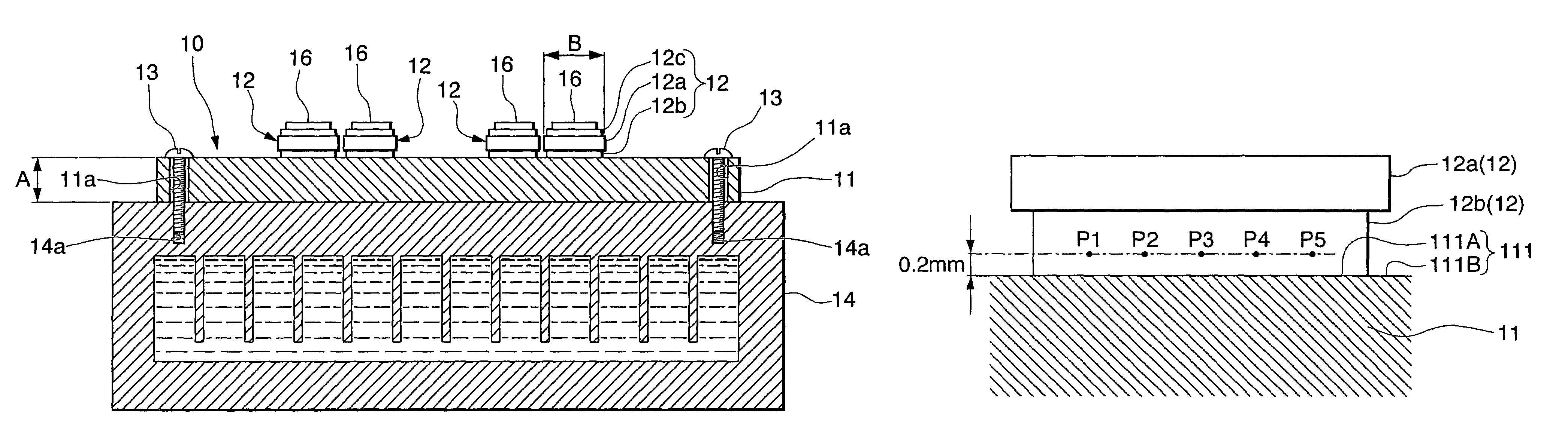
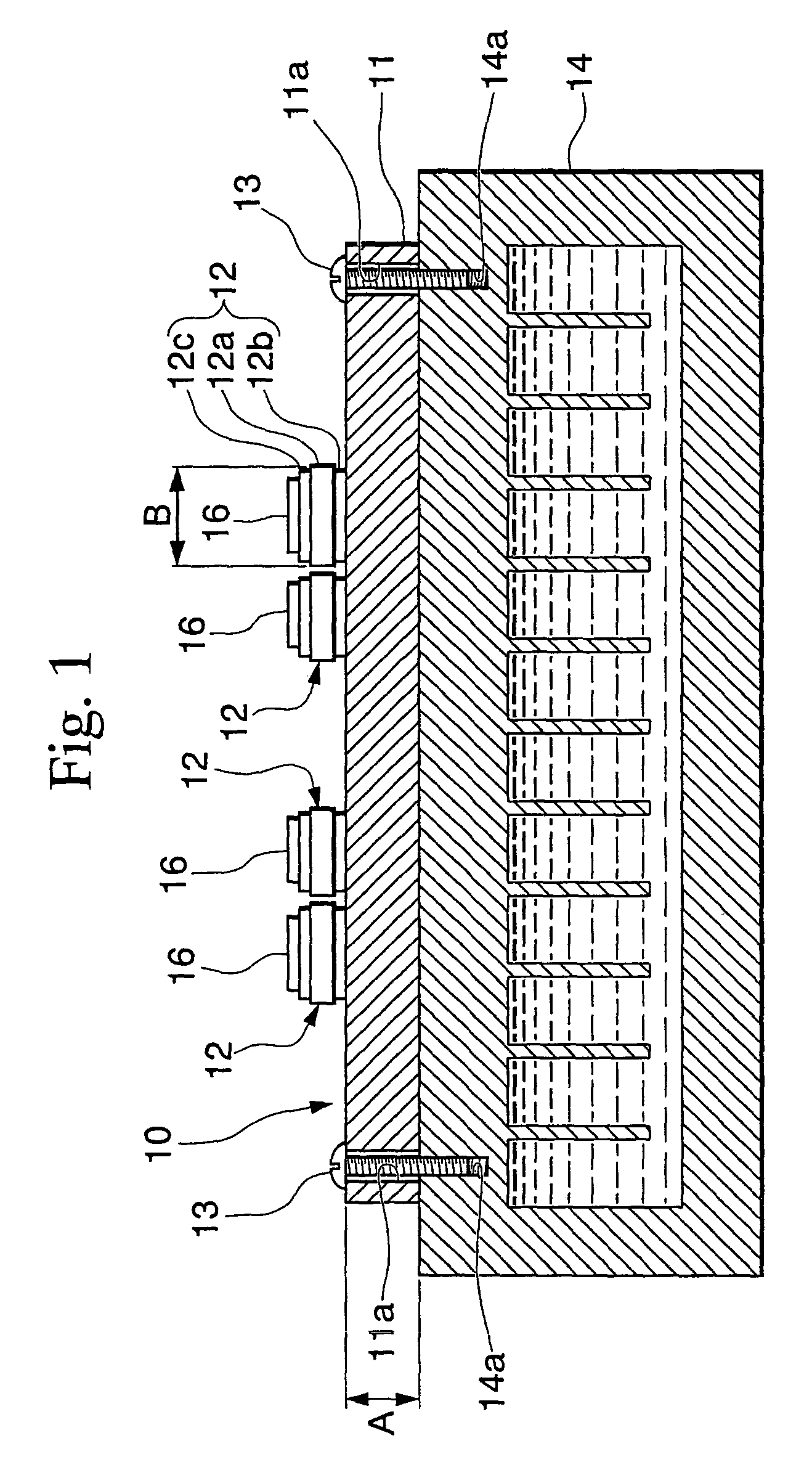
[0051]As is shown in FIG. 1, an insulated circuit board 12 was formed by stacking Al plates 12b and 12c that have vertical, horizontal, and thickness dimensions respectively of 15 mm, 15 mm, and 0.4 mm on both sides of a ceramic substrate 12a that has the same vertical and horizontal dimensions as the Al plates 12b and 12c and has a thickness dimension of 0.635 mm. This insulated circuit board 12 was prepared together with a heat discharge plate 11 formed by an Al based alloy plate having vertical, horizontal, and thickness dimensions respectively of 100 mm, 100 mm, and 3 mm. The insulated circuit board 12 that is used here has first and second Al plates 12b and 12c having a purity of 99.98 or more percent by weight bonded to both surfaces of a ceramic substrate 12a formed Si3N4.

[0052]The insulated circuit board 12 and heat discharge plate 11 were placed in a stack and then a load of 150 kPa was applied thereto and the stack was heated in a vacuum to 620° C. The stack was left in th...

example 2

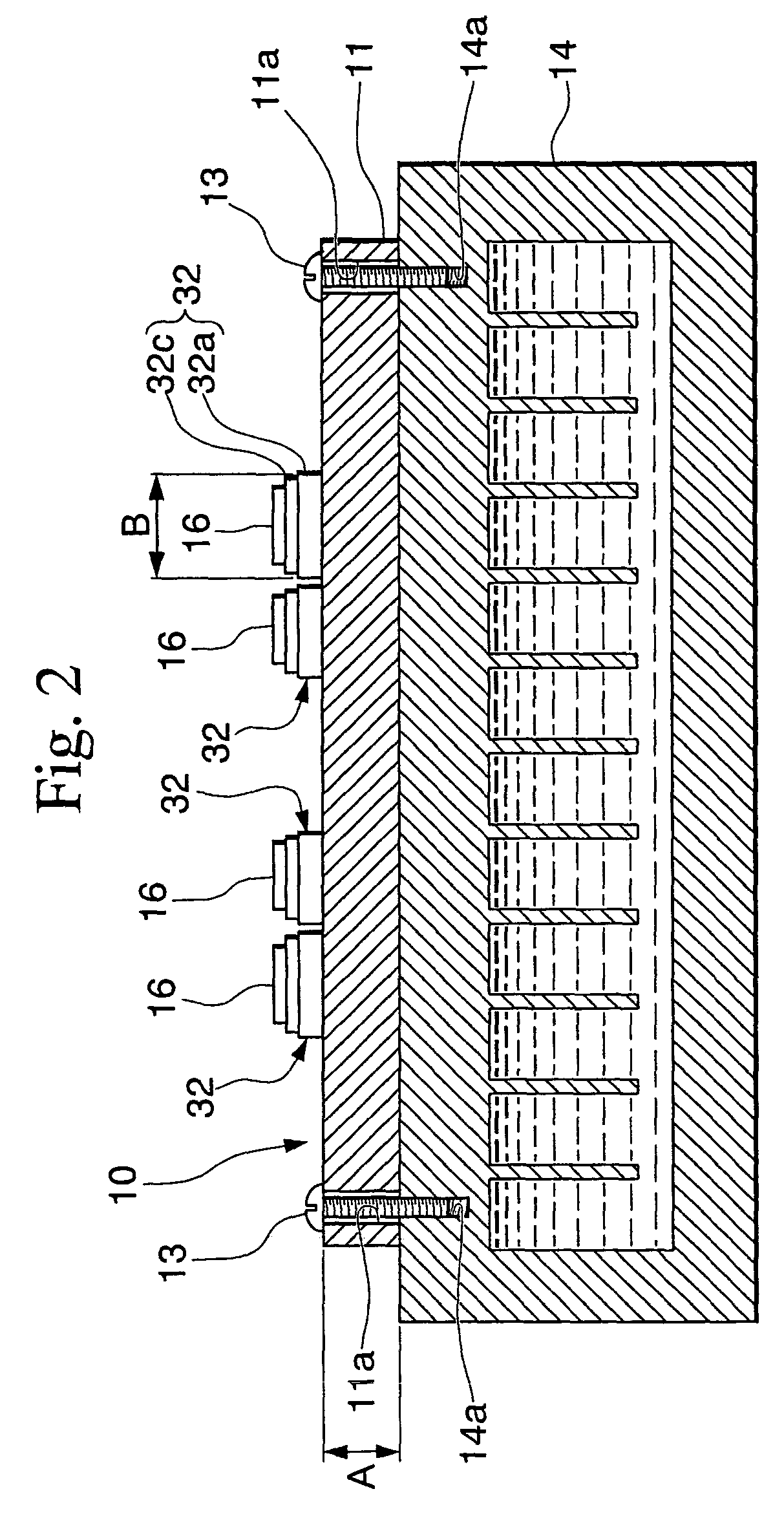
[0053]An insulated circuit board 12 formed of the same materials as the power module of Example 1 by stacking Al plates 12b and 12c that have vertical, horizontal, and thickness dimensions respectively of 20 mm, 20 mm, and 0.4 mm on both sides of a ceramic substrate 12a that has the same vertical and horizontal dimensions as the Al plates 12b and 12c and has a thickness dimension of 0.635 mm was prepared together with a heat discharge plate 11 formed by an Al based alloy plate having vertical, horizontal, and thickness dimensions respectively of 100 mm, 100 mm, and 6 mm.

[0054]A power module 10 was obtained by brazing this insulated circuit board 12 directly to the heat discharge plate 11 using Al—Si brazing material under the same conditions as in Example 1. The power module obtained in this manner was used as a test sample for Example 2.


PUM

PropertyMeasurementUnit
thicknessaaaaaaaaaa
lengthaaaaaaaaaa
lengthaaaaaaaaaa

Abstract

The present invention relates to a power module in which an insulated circuit board is fixed to one main surface of a heat discharge plate. It is an object thereof to provide a power module in which the heat discharge characteristics are improved without any marked warping being generated, and that has an extended heat cycle longevity.
In the power module 10 of the present invention, a square insulated circuit board 12 is fixed to one main surface of a heat discharge plate 11. The heat discharge plate 11 is formed of an Al based alloy plate having a thickness A of 3 to 10 mm, and the insulated circuit board 12 having a side B of 30 mm or less in length is brazed directly onto the heat discharge plate 11. It is-preferable that the brazing material used is one or two or more brazing materials selected from Al—Si, Al—Ge, Al—Cu, Al—Mg, and Al—Mn based brazing materials. It is also preferable that the insulated circuit board 12 is formed by a ceramic substrate 12a and Al plates 12b and 12c that are bonded to both surfaces thereof, and that the Al plate 12b has a purity of 99.98 or greater percent by weight.

Description

BACKGROUND OF THE INVENTION[0001]1. Field of the Invention[0002]The present invention relates to a power module in which an insulated circuit board is fixed to one main surface of a heat discharge plate.[0003]This application is based on Patent Application Nos. 2000-240580 and 2001-194034 filed in Japan, the contents of which are incorporated herein by reference.[0004]2. Background Art[0005]As is shown in FIG. 5A, a power module 1 of this type is known in which an insulated circuit board 3 is fixed to one main surface of a heat discharge plate 2. The insulated circuit board 3 is manufactured by bonding first and second aluminum (Al) plates 3b and 3c to both surfaces of a ceramic substrate 3a. The second Al plate 3c of the insulated circuit board 3 is formed by etching as a circuit having a predetermined pattern, and a semiconductor chip 4 or the like shown by the dotted chain line is mounted thereon. The first Al plate 3b of the insulated circuit board 3 is bonded to a top surface o...

Claims


Application Information

Patent Timeline
Patent Type & Authority Patents(United States)
IPC IPC(8): H05K7/20H01L23/373H05K1/03H05K3/00
CPCH01L23/3735H01L24/32H01L23/3736Y10T428/12007H01L2924/01012H01L2924/01013H01L2924/01025H01L2924/01029H01L2924/01032H01L2924/01033H01L2924/01058H05K1/0306H05K3/0058H01L2924/01005H01L2924/01006H01L2924/0132H01L2924/01014H01L2924/351H01L2924/15787C04B2237/407H01L2224/2612H01L2924/00
Inventor NAGATOMO, YOSHIYUKINAGASE, TOSHIYUKISHIMAMURA, SHOICHI
Owner MITSUBISHI MATERIALS CORP
Why Eureka
Try Eureka