
Method and apparatus of data transmission

a data transmission and data technology, applied in the field of methods and apparatuses for transmitting data, can solve the problems of high accuracy and interference between frequencies, and achieve the effect of suppressing the degradation of the code error ra

Inactive Publication Date: 2006-03-28
KOKUSA ELECTRIC CO LTD
View PDF16 Cites 34 Cited by
  • Summary
  • Abstract
  • Description
  • Claims
  • Application Information

AI Technical Summary

Benefits of technology

[0014]A second symbol is a symbol in which the amplitude is fixed, and the frequency thereof is changed at fixed rate with time from the lower frequency to the upper frequency within the transmission band over the symbol period of time (hereinafter, referred to as “a sweep symbol” for short, when applicable) and is generated in a sweep symbol generator 55. The auto-correlation function of this sweep symbol has a sharp peak value, and hence by utilizing this property, it is possible to acquire a specific time point on the time base with higher accuracy than that of the null symbol.
[0036]By executing the above-mentioned processing, since the reception sample value sequence is synchronized with the count value of the frame counter 68, it is possible to be accurately aware of a specific time point such as a transmission point of the frame or the symbol on the reception sample value sequence.
[0079]In the light of the foregoing, the present invention is intended to solve the above-mentioned problems, and it is therefore an object of the present invention to provide an OFDM digital transmission method in which the inter-symbol interference is less and hence the C / N ratio is better and an apparatus employing the same, and a method and an apparatus for receiving an OFDM signal.
[0083]According to one feature of the present invention, an effective correlation peak is detected in which a value of a correlation peak is equal to or larger than a predetermined value, and the inter-symbol interference becomes minimum and on the basis of the effective correlation peak thus detected, a control signal is generated in accordance with which the reception sampling clock synchronous processing and the control for the frame timing and the symbol timing of the receiver are carried out.
[0090]In such a manner, the reception sampling clock synchronous processing and the control for the frame timing and the symbol timing of the receiver are carried out on the basis of the optimal correlation peak, whereby the inter-symbol interference can be suppressed and the degradation of the code error rate can also be suppressed.

Problems solved by technology

On the other hand, since in the OFDM system, the frequency interval between the carriers is narrow, interference between the carriers due to the carrier frequency error between the transmitter and the receiver and due to the sampling clock frequency error of the demodulation system may readily occur, and hence high accuracy is required for those frequencies.

Method used


Image

  • Method and apparatus of data transmission
  • Method and apparatus of data transmission
  • Method and apparatus of data transmission

Examples


Embodiment Construction

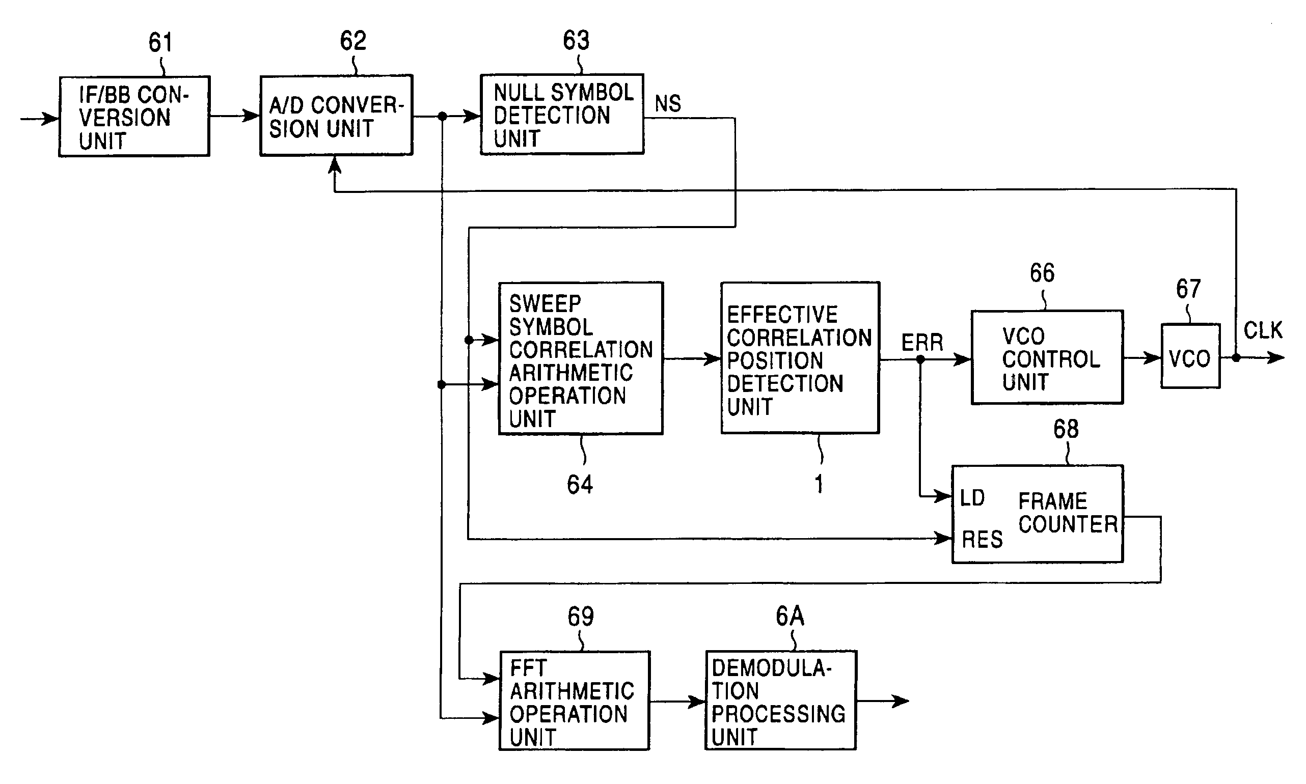
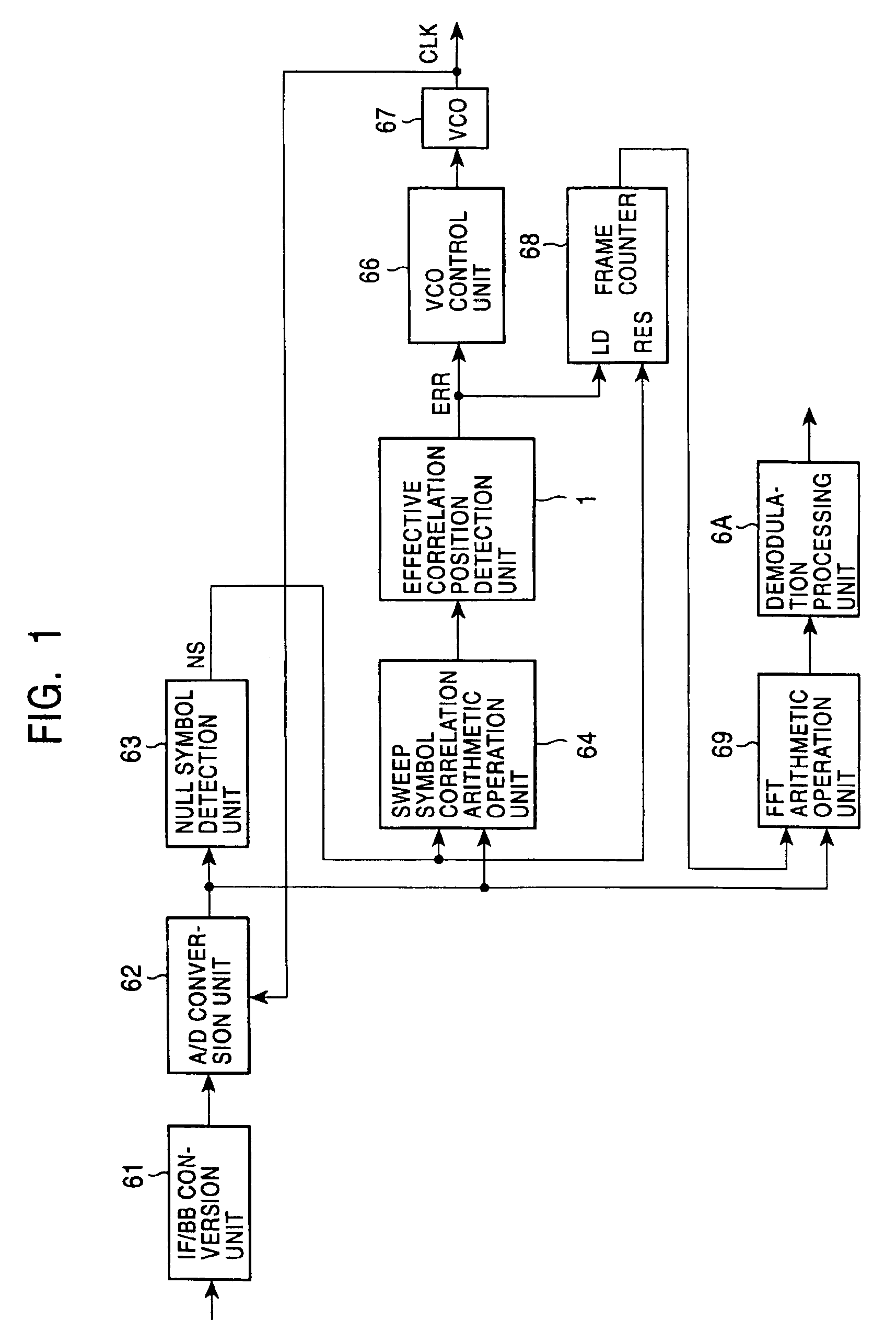
[0120]A digital transmission according to an embodiment of the present invention will hereinafter be described in detail with reference to the accompanying drawings. In this connection, in the figures, the same parts are designated with the same reference numerals.

[0121]FIG. 1 is a block diagram showing a configuration of a receiver of a digital transmission apparatus according to one embodiment of the present invention.

[0122]In FIG. 1, a received signal transmitted from a transmitter like one shown in FIG. 5 to reach the receiver through a transmission path is first converted from a signal having a inter frequency (IF) band to a signal having a base band frequency band in an IF / BB conversion unit 61, as described with reference to FIG. 6.

[0123]An output signal from the IF / BB conversion unit 61 is subjected to the analog / digital conversion in an A / D conversion unit 62 using a reception sampling clock. A reception sample value sequence signal acquired from the A / D conversion unit 62 ...


PUM


Abstract

A data transmission apparatus employing an orthogonal frequency division multiplex system. A receiver included therein analyzes a cross-correlation value sequence signal (CT) which has been acquired from the arithmetic operation of the correlation between a received signal and a predetermined symbol signal to detect an effective correlation peak in which the inter-symbol interference becomes minimum, and on the basis of the effective correlation peak thus detected, carries out the processing of synchronizing a reception sampling clock, and the control for the frame timing and the symbol timing of the receiver.

Description

CROSS-REFERENCES TO RELATED APPLICATIONS[0001]The present invention relates to the following U.S. Patent application assigned to the assignee of the present invention. U.S. Ser. No. 09 / 099390, Atushi Miyasita et al. filed on Jun. 18, 1998 entitled “OFDM MODULATOR AND OFDM MODULATION METHOD FOR DIGITAL MODULATED WAVE HAVING GUARD INTERVAL”, U.S. Ser. No. 09 / 096454, Seiichi Sano et al. filed on Jun. 11, 1998 entitled “DATA TRANSMISSION APPARATUS AND RECEIVING APPARATUS USING ORTHOGONAL FREQUENCY DIVISION MULTIPLEX MODULATION SYSTEM” and U.S. Ser. No. 09 / 203564, Seiichi Sano et al. filed on Dec. 2, 1998 entitled “SYNCHRONIZATION DETECTION METHOD FOR DATA TRANSMISSION APPARATUS AND DATA TRANSMISSION APPARATUS USING THE SAME”.BACKGROUND OF THE INVENTION[0002]The present invention relates in general to a method and an apparatus for transmitting data, and more particularly to a method and an apparatus for transmitting data employing an OFDM (Orthogonal Frequency Division Multiplex) system,...

Claims


Application Information

Patent Timeline
Patent Type & Authority Patents(United States)
IPC IPC(8): H04Q7/24H04J11/00H04L7/00H04L27/26
CPCH04L27/2655H04L27/2656H04L27/2657H04L27/2662H04L27/2675H04L27/2676
Inventor NAKADA, TATSUHIRO
Owner KOKUSA ELECTRIC CO LTD
Learn More