
Method for producing a cam for a camshaft

a camshaft and camshaft technology, applied in the direction of cams, couplings, valve details, etc., can solve the problems of cams being shortened and bent to a considerable extent, risk of cam cracks, and prone to tilting

Inactive Publication Date: 2006-04-04
MERZ KARL
View PDF22 Cites 12 Cited by
  • Summary
  • Abstract
  • Description
  • Claims
  • Application Information

AI Technical Summary

Benefits of technology

"The present invention relates to a method for producing cams for camshafts in a more efficient and cost-effective way, as well as a method for producing a camshaft that can be fixed on the shaft by welding. The invention also provides a cam that can be easily fixed on the shaft by welding, which eliminates the need for rolling of the shaft and reduces the time-consuming process of remachining. The method involves using a cam that is produced from a profile strip by bending the ends of the strip together or assembling multiple profile strip pieces in a circumferential direction. The invention allows for faster and more cost-effective production of cams and camshafts, with greater strength, and is more economical overall."

Problems solved by technology

However, the method has various disadvantages:During rolling, the shafts are lengthened and bent to a considerable extent.
Since a minimum thickness is usually prescribed for this hardening zone, it, too, has to be overdimensioned from the outset.When the cams are being pressed on, it may happen that they tilt somewhat, because said groove systems do not necessarily provide a straight fit of the cams on the shaft.
These tolerances, too, have to be taken into account by means of a sufficient oversize and subsequently eliminated again by grinding.When the cams are pressed on forcibly, there is the risk of the formation of cracks in the cams, this having the effect of a reject source.Production is highly time-intensive due to the many necessary machining steps and the considerable degree of remachining after the cams have been pressed on.
However, this is usually not sufficiently firm to withstand the torques which occur, for example, on the cams in an automobile engine.

Method used


Image

  • Method for producing a cam for a camshaft
  • Method for producing a cam for a camshaft
  • Method for producing a cam for a camshaft

Examples


Embodiment Construction

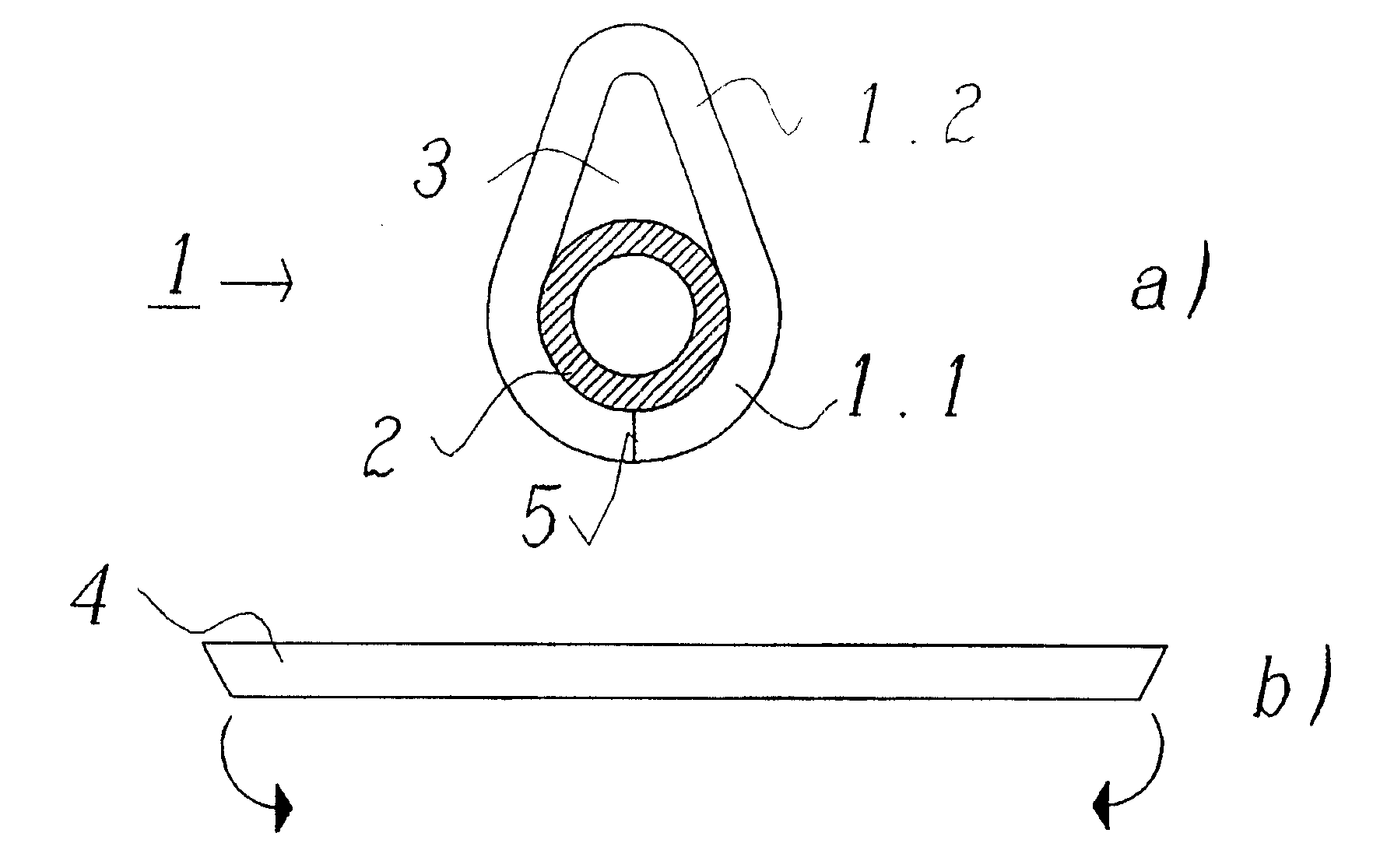
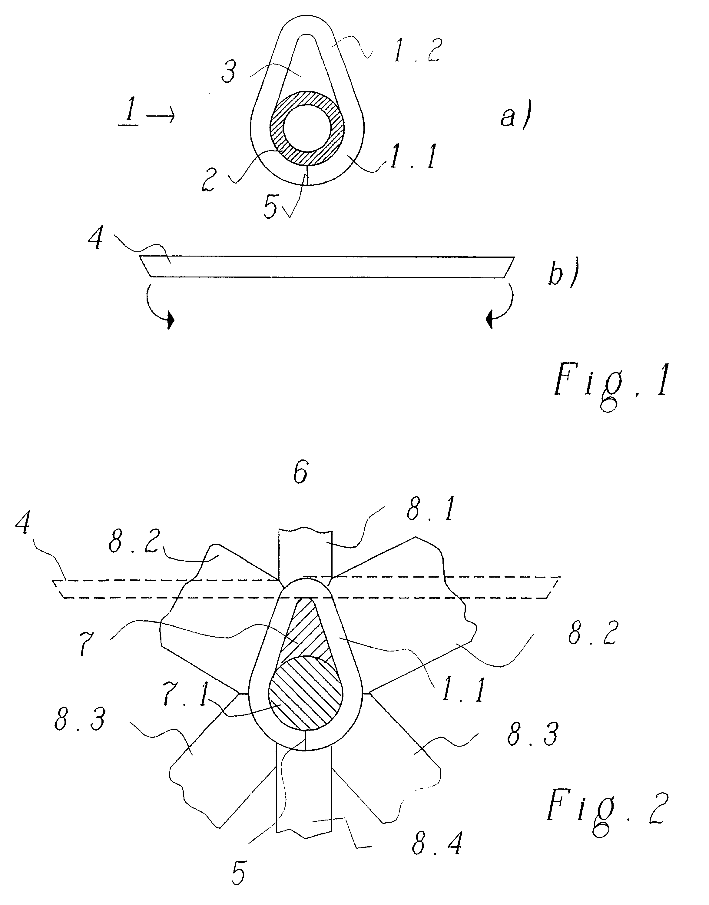
[0033]In FIG. 1, under a), 1 designates a cam according to the invention which is fastened on a hollow-cylindrical shaft 2. The cam 1 has a first portion 1.1, along which it is in bearing contact on the shaft 2 and partially surrounds the latter, and a second portion 1.2 which projects from the shaft and surrounds a cavity 3. The cavity 3 has the advantage that it makes the cam 1 lighter and reduces its moment of inertia. The weight of the entire camshaft and its rotational resistance are thereby also reduced.

[0034]The cam 1 is produced from a profile strip by its ends being bent together. Such a profile strip 4 is shown in FIG. 1 under b), the profile strip 4 still being straight and unbent here. The bending direction of the profile strip 4 is indicated by arrows.

[0035]Preferably, the profile strip 4 is bent in such a way that, after bending, its ends form a butt joint 5 and its end faces butt against one another over their area. For this purpose, it may be advantageous to bevel th...


PUM

PropertyMeasurementUnit
thicknessaaaaaaaaaa
thicknessaaaaaaaaaa
heightaaaaaaaaaa

Abstract

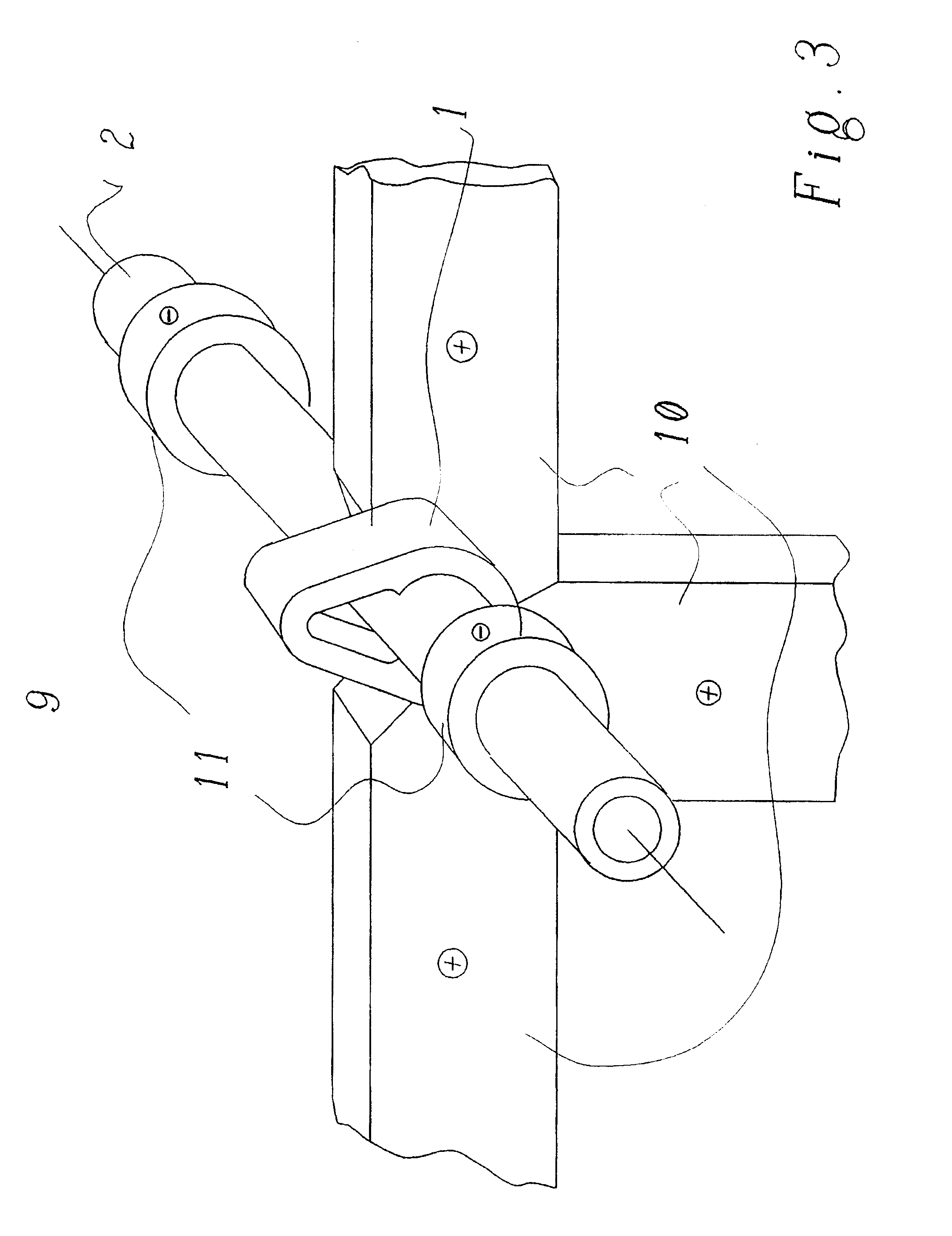
The invention relates to a method for producing cams (1) for a camshaft. The cams are produced by bending together the ends of long profile strips (4) or by bending and putting together several pieces of profile strips in a circumferential direction. Cams produced in such a way are preferably welded onto the shaft. The invention also relates to suitable welding methods such as resistance welding, laser-beam or electron-beam welding and corresponding devices.

Description

TECHNICAL FIELD[0001]The present invention relates to a method for producing a cam for a camshaft, such as is used, for example, in internal combustion engines for automobiles, with a cylindrical shaft and with a plurality of cams fixed on the latter.[0002]Camshafts of this type, assembled from a plurality of individual parts, are used increasingly instead of camshafts produced by casting or forging.[0003]The invention relates, further, to the production of a camshaft, using at least one cam of the novel type described below here.PRIOR ART[0004]In the production of cams for camshafts, normally blanks are first obtained by a rod-shaped solid material being cut to length. Only then is the passage orifice for the shaft produced in these. Finally, usually also axially oriented grooves are reamed out in the passage orifice and the outer surface of the cams is hardened.[0005]To fix the usually plurality of cams on the shaft, various methods are known in the prior art:[0006]In a first such...

Claims


Application Information

Patent Timeline
Patent Type & Authority Patents(United States)
IPC IPC(8): B21K1/12F01L1/04B21D53/84B23P15/00F01L1/047F01L1/08F16D1/068F16H53/02
CPCB21D53/845B23P15/00F01L1/047F16D1/068F16H53/025F01L1/08B23P2700/02Y10T29/49293Y10T74/2101
Inventor MERZ, KARL
Owner MERZ KARL
Learn More