Multiple outlet air path for a clothes dryer

a clothes dryer and airflow technology, applied in the field of electric clothes dryers, can solve the problems of large cost, long dry time, and integration of complete laundry centers into living space, and achieve the effects of accelerating drying clothes, reducing plastering of clothes, and increasing the speed of airflow

Active Publication Date: 2006-04-04
WHIRLPOOL CORP
View PDF6 Cites 73 Cited by
  • Summary
  • Abstract
  • Description
  • Claims
  • Application Information

AI Technical Summary

Benefits of technology

[0013]These problems and others are solved by the present invention of a clothes dryer comprising a heat pump, a drum, an inlet in the drum fluidly connecting the heat pump to the drum, and first and second outlets in the drum. Each outlet is covered by a grill, and spaced from the other and from the inlet to exhaust air from the drum. A fan is provided for generating a flow of air from the heat pump into the drum through the inlet and out of the drum through the first and second outlets. With this structure, the velocity of the flow of air can be increased through the drum with minimal pressure drop between the inlet and the outlets to accelerate drying clothes in the drum with less plastering of clothes against the grill at either of the outlets.

Problems solved by technology

The trend in many newer homes is to integrate complete laundry centers into the living space, typically at a considerable expense.
These strips serve to measure gross detection of whether the load is wet or not and typically do not quantify how wet or how dry.
Heat pump dryers tend to have very long dry times, which make them unacceptable in the North American market.
But these solutions lead to other problems.
Air temperatures from a heat pump are essentially limited by the choice of refrigerant.
Standard R-22 based heat pump systems do not lend themselves to delivering high temperatures.
As airflow exceeds 200 cfm, increased pressure drop across the drum tends to cause clothing in the drum to be drawn onto the outlet grill and held in place, which creates a significant problem in maintaining adequate air flow.
Added to this complication is the likelihood of lint migration beyond the lint screen into the region of the heat exchangers due to increased airflow.
This creates problems for system geometry and the design of the heat exchangers and heat transfer apparatus.
In conventional electric dryers, increasing air temperature comes at the cost of greater energy expenditure.
Also, the problem of clothes plastering to the outlet grill with increased airflow remains.

Method used


Image

  • Multiple outlet air path for a clothes dryer
  • Multiple outlet air path for a clothes dryer
  • Multiple outlet air path for a clothes dryer

Examples


Embodiment Construction

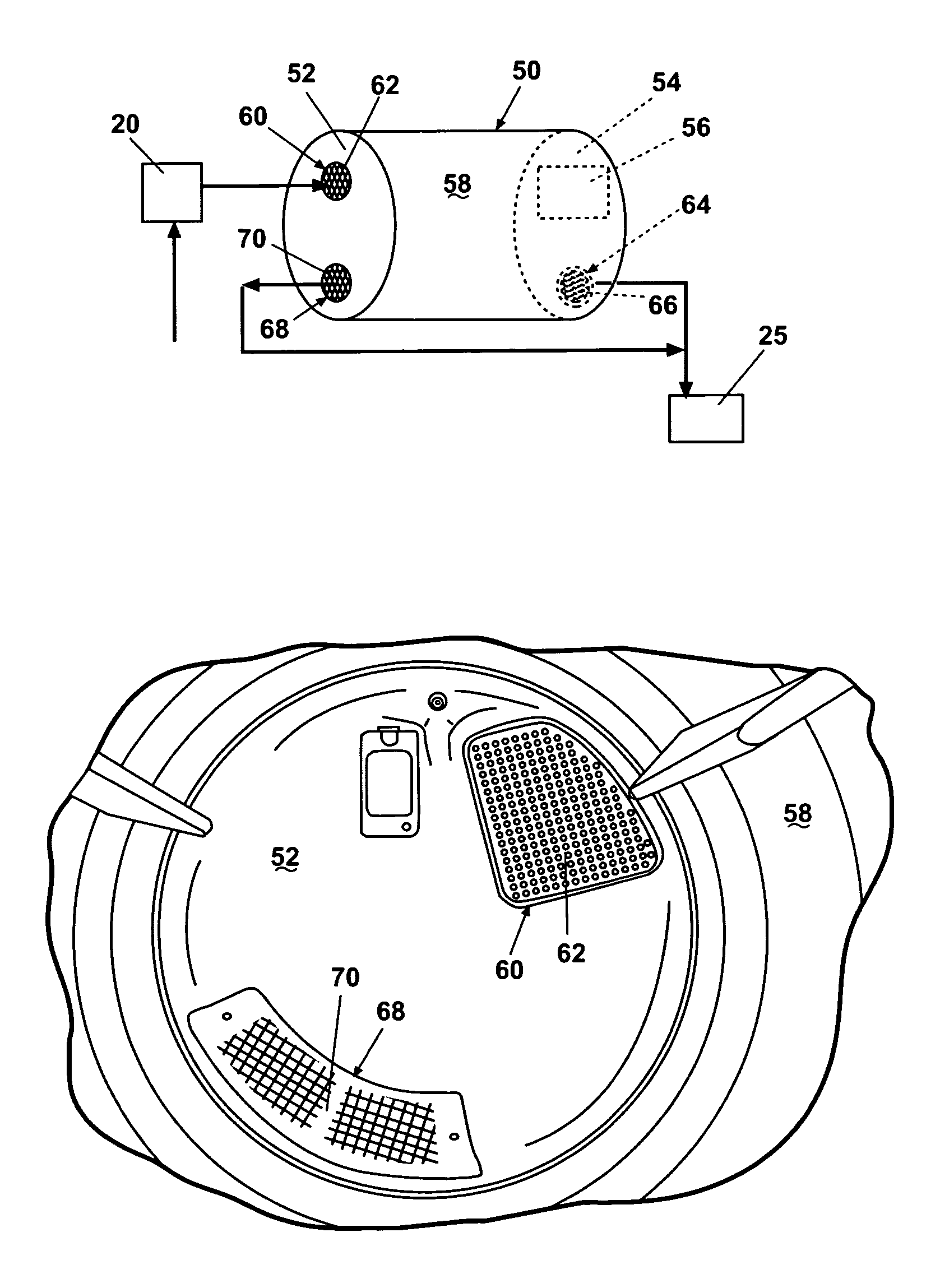
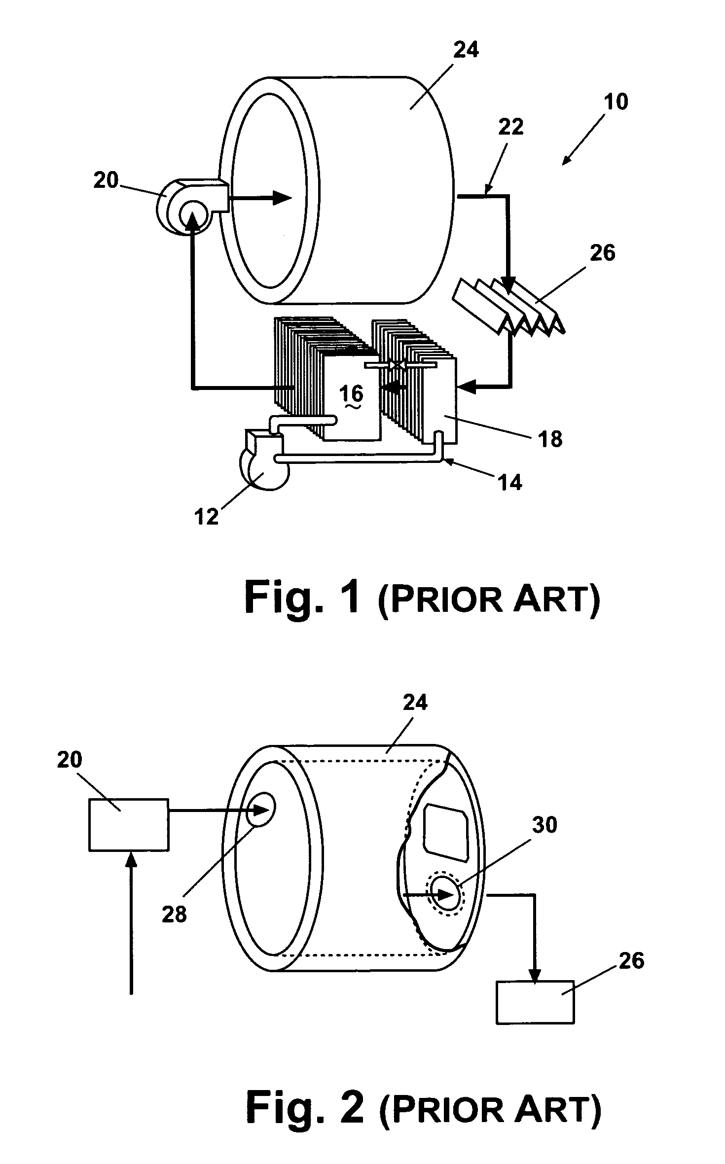
[0027]The invention relates to the air flow path through the drum of a dryer. A preferred embodiment, as set forth herein, appears in a heat pump dryer having an overall configuration not unlike that shown in FIG. 1. For the heat pump embodiment according to the invention, it was found desirable to incorporate most of the components associated with a heat pump system (compressor, evaporator, condenser, tubing, etc.) into a conventional resistance heater dryer cabinet. Preferably, the heat pump will draw 2.2 Kilowatts of power utilizing 250 cfm of airflow.

[0028]A reciprocating compressor is preferred, mainly for reliability reasons. The pressure ranges under which normal operation occurs (in order to maximize condenser temperatures) suggest the use of a more reliable reciprocating compressor. A rotary compressor design is an acceptable alternative, if reliability is not a primary concern.

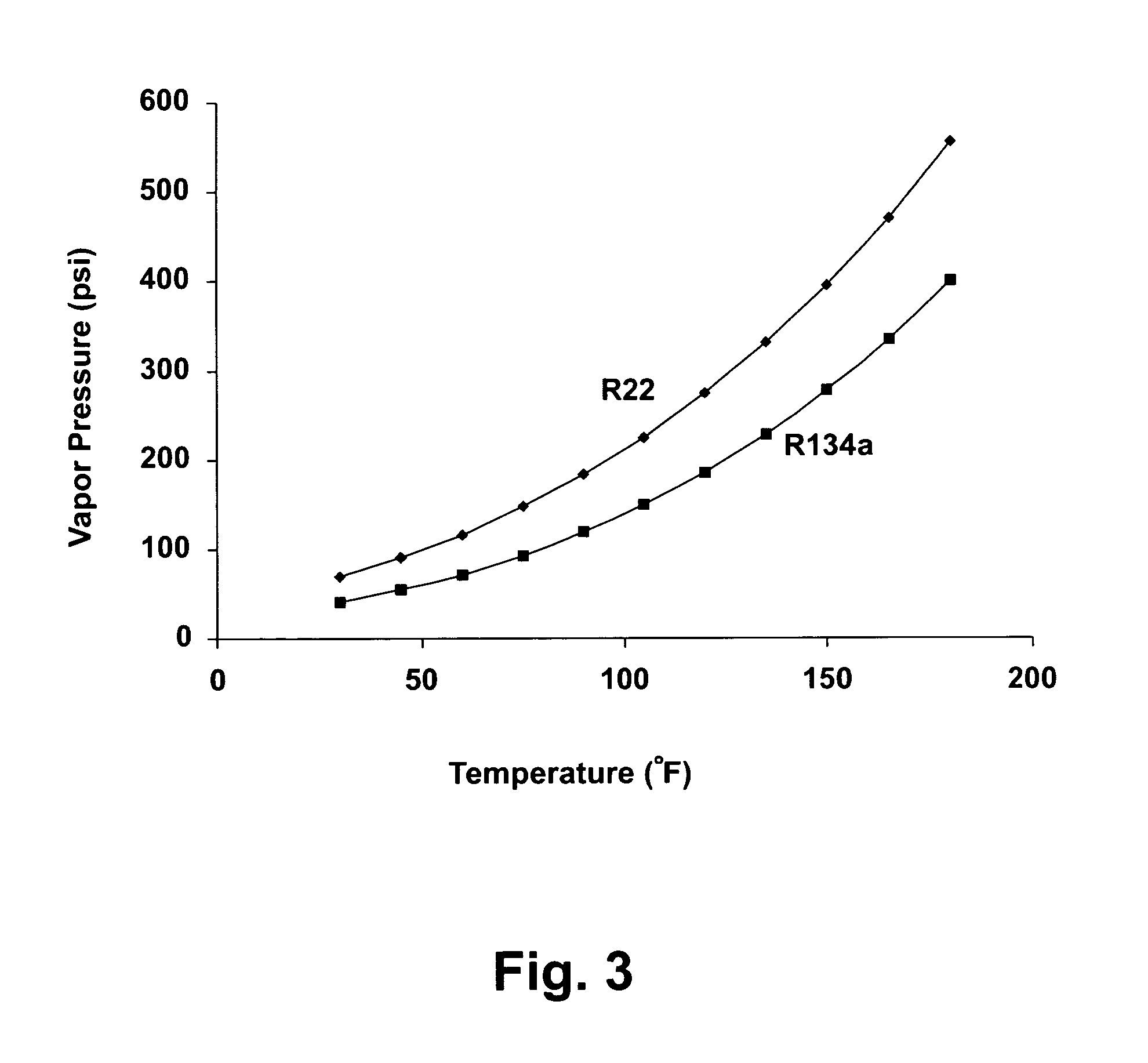
[0029]In order to achieve the highest possible air temperatures, the preferred embodiment uses R-...


PUM


Abstract

A clothes dryer has a heat source, preferably a heat pump, a rotating drum, and means to generate flow of air from the heat source to an inlet in the drum. At least two outlets are separated from each other in the drum to enable higher air flow rates without increase in pressure drop, resulting in reduced drying time.

Description

[0001]This patent application claims the benefit of Provisional application 60 / 557,073, filed Mar. 26, 2004.BACKGROUND OF THE INVENTION[0002]1. Field of the Invention[0003]The invention relates to electric clothes dryers and more particularly to the airflow paths within the dryer.[0004]2. Description of the Related Art[0005]Laundry areas in homes are moving out of the basement. The trend in many newer homes is to integrate complete laundry centers into the living space, typically at a considerable expense. Combining this trend with a greater awareness of energy conservation, especially water conservation, has led to a significant increase in demand for high-end front-loading washing machines with many consumer-focused performance attributes. Meanwhile, in general, the clothes dryer has changed very little.[0006]Most standard electric dryers available today in North America operate with a resistance-type heating element at a fixed wattage and a fixed airflow rate (varying only in res...

Claims


Application Information

Patent Timeline
Patent Type & Authority Patents(United States)
IPC IPC(8): F26B11/02D06F58/02
CPCD06F58/206D06F58/02
Inventor CASEY, STEVEN MICHAELMARTIN, DAVID MICHAELDIECKMANN, JOHN THOMASPESCATORE, PETER FRANCISCARBONE, PHILIP C.ELLIS, JR., WARREN JAMESCHERNETSKI, FREDERICK E.
Owner WHIRLPOOL CORP
Why Eureka
Try Eureka