

Apparatus for rapidly measuring liquid levels and volume of groundwater within wells that eliminates cross contamination between wells
a technology of liquid level and well, applied in the field of measuring liquid level in groundwater wells, can solve the problems of difficult to completely remove the sensor probe and tape, time-consuming and consequently costly, and run the risk of being exposed to contaminants in the well, so as to prevent the buildup of highly viscous liquids and prevent the exposure of the connection
- Summary
- Abstract
- Description
- Claims
- Application Information
AI Technical Summary
Benefits of technology
Problems solved by technology
Method used
Image

Examples
Embodiment Construction
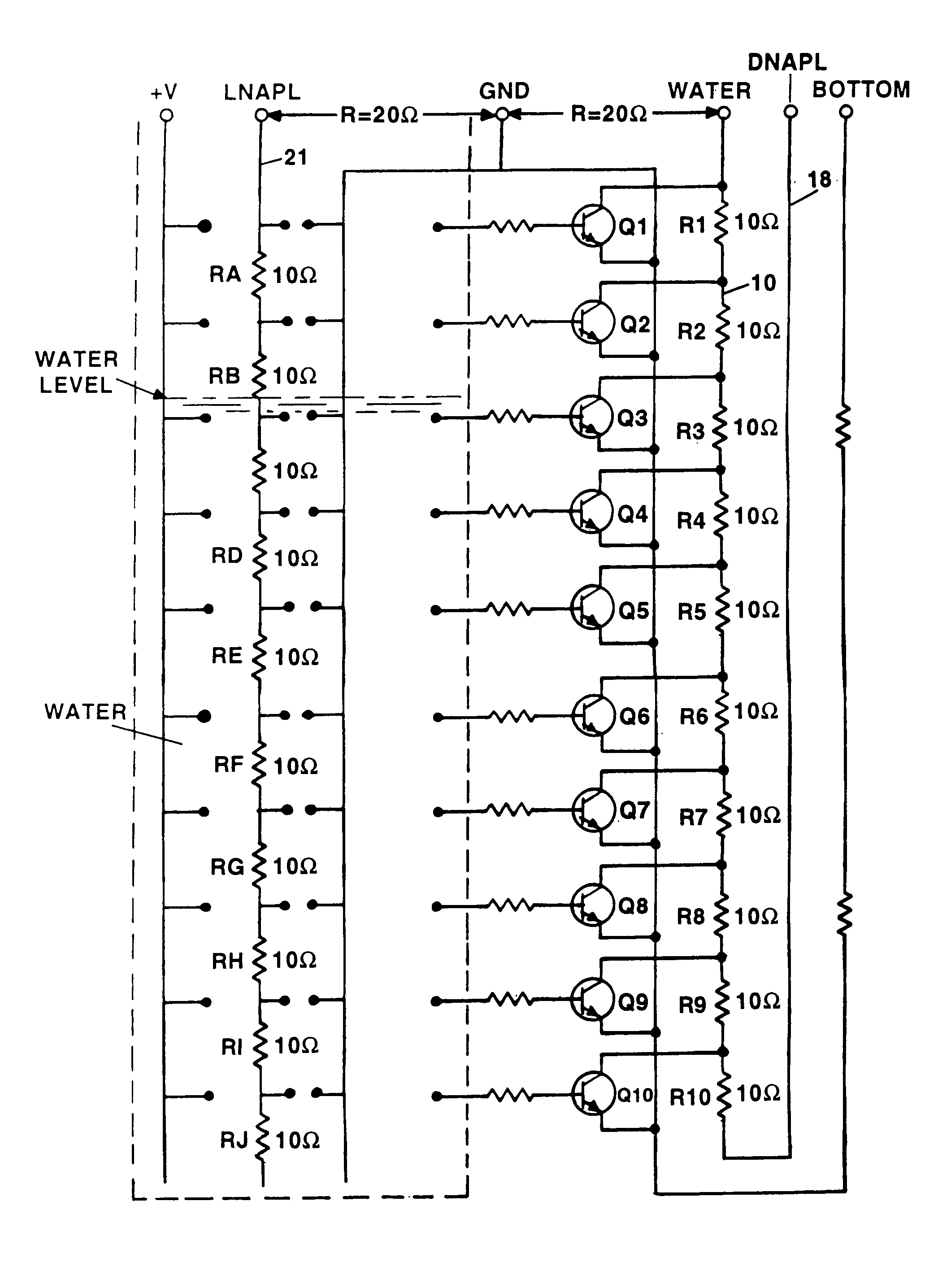
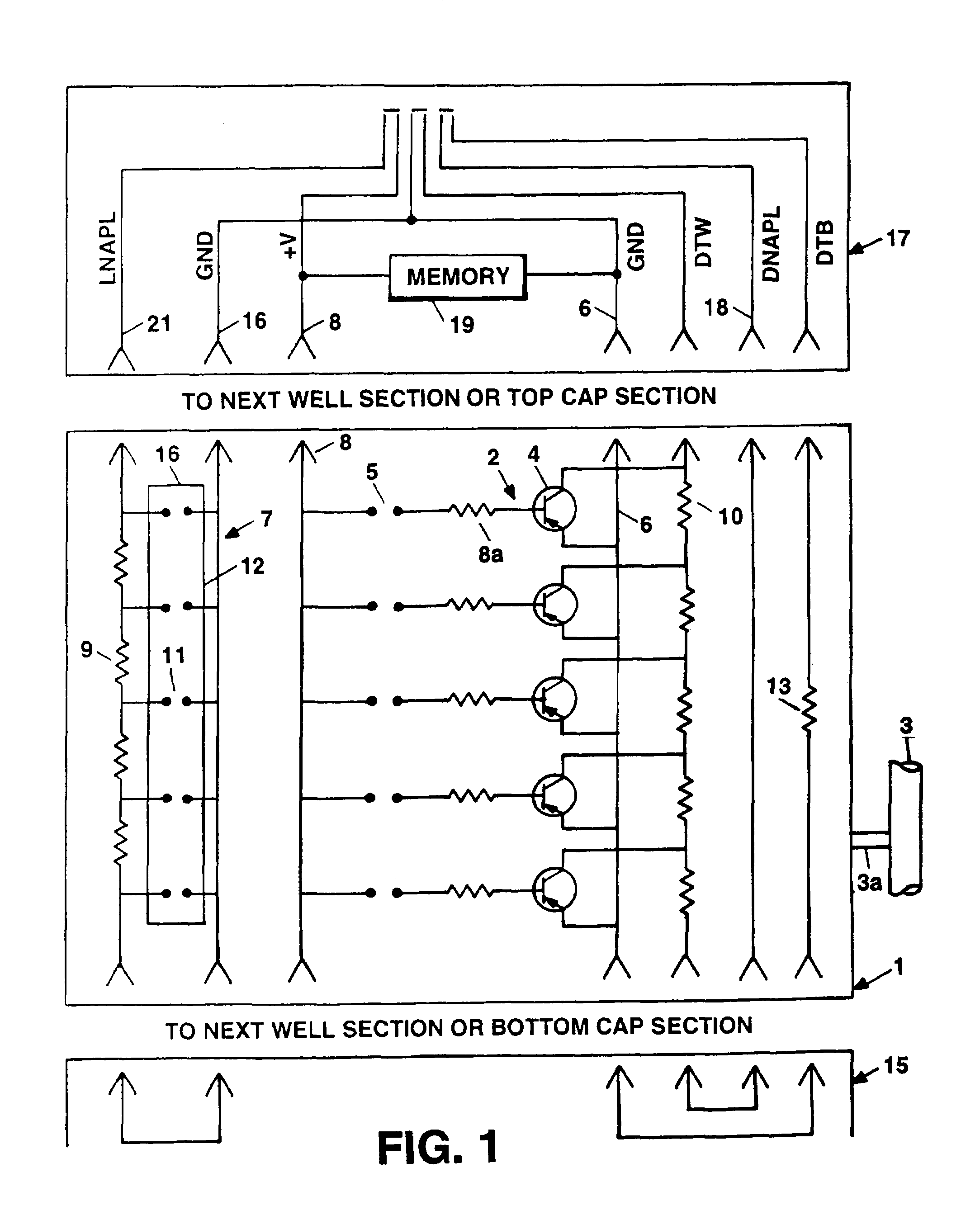
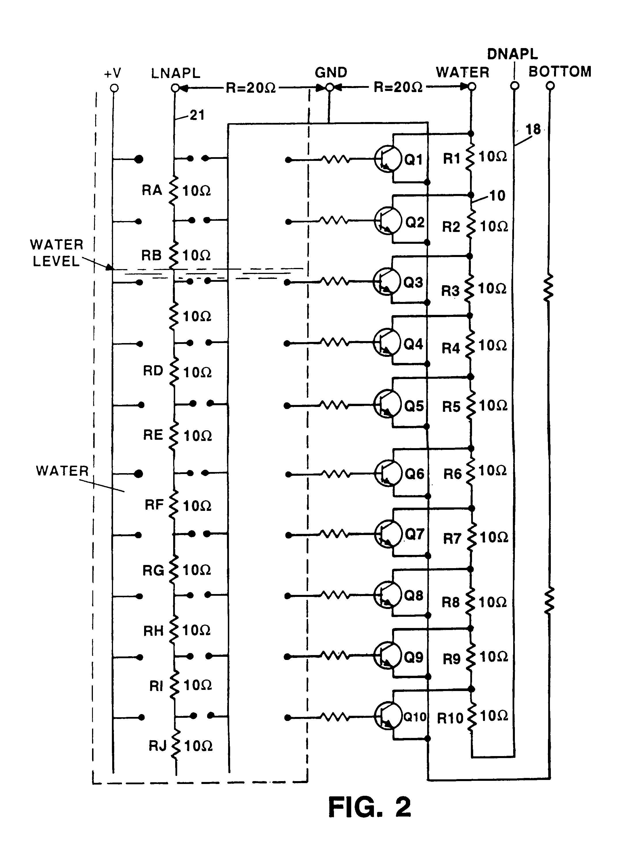
[0013]An elongate thin film sensor tape circuit 1, in FIG. 1, is incorporated into the inside annulus of a groundwater well casing 3 so that is in contact with any liquid present in the well. The sensor tape's outer jacket has a smooth non-stick surface to prevent build up of highly viscous liquids and includes a conductive resistive circuit that detects the level of water that conducts current in contrast with contaminants. An array of tiny stainless steel electrodes 5 exposed at the surface of the sensor tape at 0.01-foot intervals along the length of the sensor tape, sense the presence of water such that an electrical resistance measured at the top of the well casing is proportional to the depth of the water in the well. The thin film sensor tape circuit also includes a hydrostatic sensing circuit 7 that is sensitive to the actuation pressure of any liquid, (water or NAPL), in which it is immersed. This circuit consists of a network of resistors 9 with an intervening pair of cont...
PUM
 Abstract
Description
Claims
Application Information