Attitude sensor

a technology of attitude sensor and sensor package, which is applied in the direction of vibration measurement in solids, sonic/ultrasonic/infrasonic transmission, instruments, etc., can solve the problems of difficult to predict the settlement of the package, the complexity and size of the sensor package of the gimbal is significantly increased, and the complexity of the three-dimensional space is not known in general, so as to achieve accurate and accurate attitude sensing. , the effect of high performance and low cos

Inactive Publication Date: 2006-04-04
OPTASENSE HLDG LTD
View PDF15 Cites 59 Cited by
  • Summary
  • Abstract
  • Description
  • Claims
  • Application Information

AI Technical Summary

Benefits of technology

[0016]In accordance with the present invention, an attitude sensing device is provided with an electro-mechanical attitude sensor which enables the required accuracy and performance in attitude sensing to be achieved. However, rather than providing a dedicated data link for the attitude sensor to enable the attitude sensor's reading to be output, converter logic is provided within the attitude sensing device for converting the electrical signal output by the electro-mechanical attitude sensor into a stimulus signal. This stimulus signal is of a type which the fibre optic sensor within the package is sensitive to, and accordingly the fibre optic sensor is responsive to the stimulus signal to cause a variation in at least one predetermined property of an optical signal transmitted through the fibre optic sensor. The stimulus signal is encoded such that the attitude of the reference axis of the package is determinable from the variation of the predetermined property of the optical signal.
[0017]By this approach, the measurement made by the electro-mechanical attitude sensor is converted into a form where it is output using the standard mechanism provided for transmitting the outputs of the fibre optic sensor itself, and hence completely avoids the requirement to provide a dedicated data transmission system to carry the output signal from the attitude sensor. Typically, the signals generated by the fibre optic sensor within the package are output over a fibre optic cable, and in accordance with the present invention the output of the electro-mechanical attitude sensor is also converted into a form where it can be output by the fibre optic sensor over the fibre optic cable.
[0018]Hence, in summary, the present invention provides a high performance, low cost, reliable technique for integrating existing electro-mechanical attitude sensors within a package containing a fibre optic sensor by interfacing the attitude sensor with the existing all-optical seismic sensor and data transmission system. This then enables an array of packages to be produced to form a fully fibre optic array.
[0031]However, given the earlier discussions, it would clearly be desirable to avoid the need to provide any dedicated cabling to the attitude sensing device merely to enable the command signal to be passed to the receiver. Accordingly, in one embodiment, the command signal may be formed as a predetermined vibration sequence, and the receiver may be formed by the vibration source, the vibration source being further arranged to convert the received command signal into an electrical signal used to switch on the attitude sensor. Hence, in such embodiments, the vibration source has a bi-directional operation, such that it can convert an electrical signal (i.e. the drive signal) into a vibration sequence, and conversely convert vibrations into a suitable electrical signal to be routed to the attitude sensor to turn it on and off.

Problems solved by technology

To interpret the signals generated by the sensors in the array as a result of such a process, it is important to know the orientation of each package, and hence the orientation of the sensors within each package, and in typical deployment conditions, this can be difficult.
For example, when such an array is deployed onto the seabed, it is difficult to predict how the packages will settle on to the seabed, and so the orientation of each package in three dimensional space is not in general known.
The use of mechanical gimbals can significantly increase the complexity and size of each sensor package, and in certain deployments has been found to be unreliable.
However, at the current time, no all optical attitude sensors with the required performance are deemed to currently exist.
Hence, whilst it is clear that an all optical seismic seabed array of fibre optic sensors will require attitude sensors, none of the existing all-optical attitude sensors are likely to give the required performance.
This would clearly increase cabling requirements within the arrays, add significantly to their complexity, and detract from the general perceived benefits described above of using an array consisting of fibre optic sensors.

Method used


Image

  • Attitude sensor
  • Attitude sensor
  • Attitude sensor

Examples


Embodiment Construction

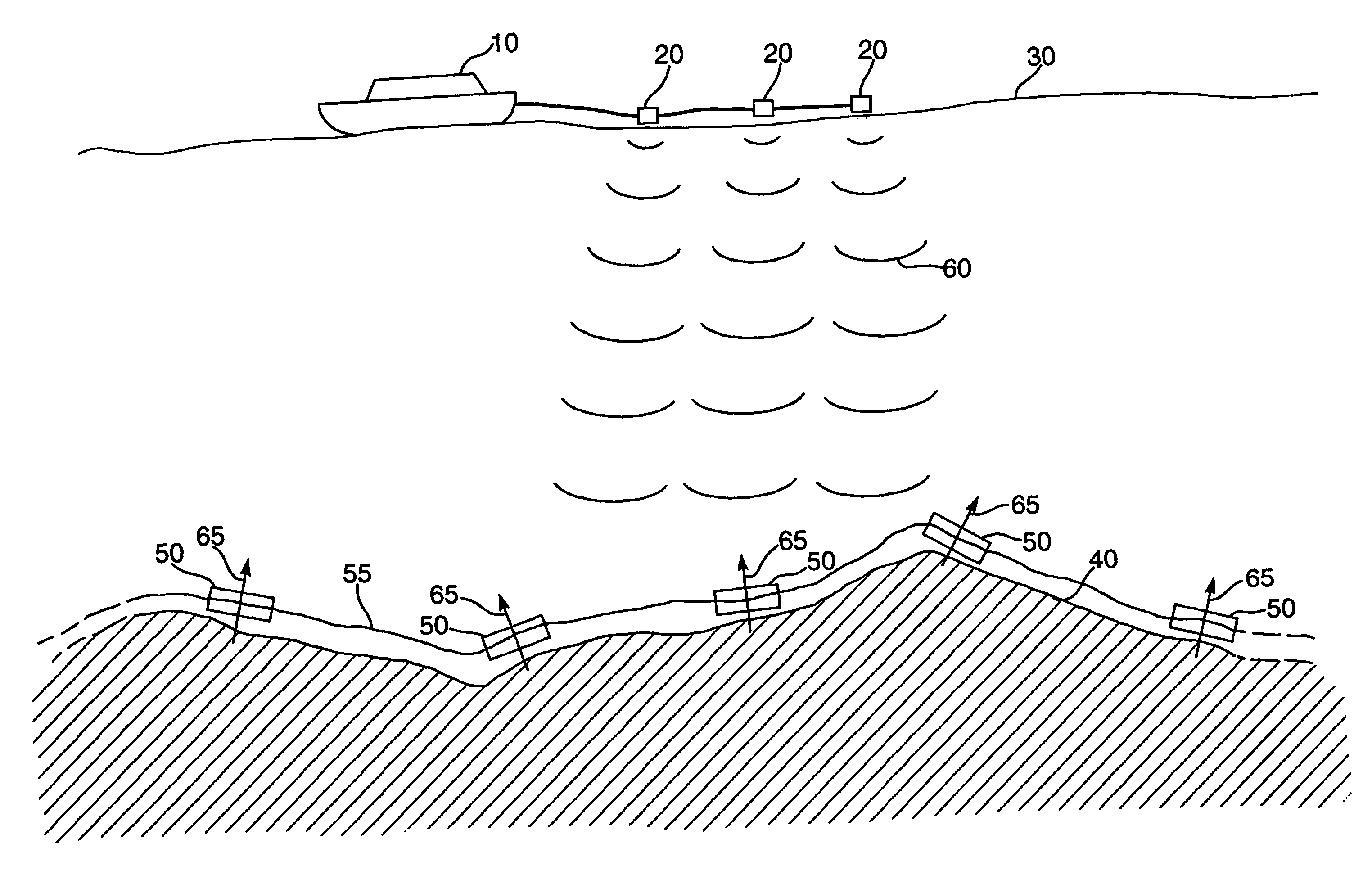
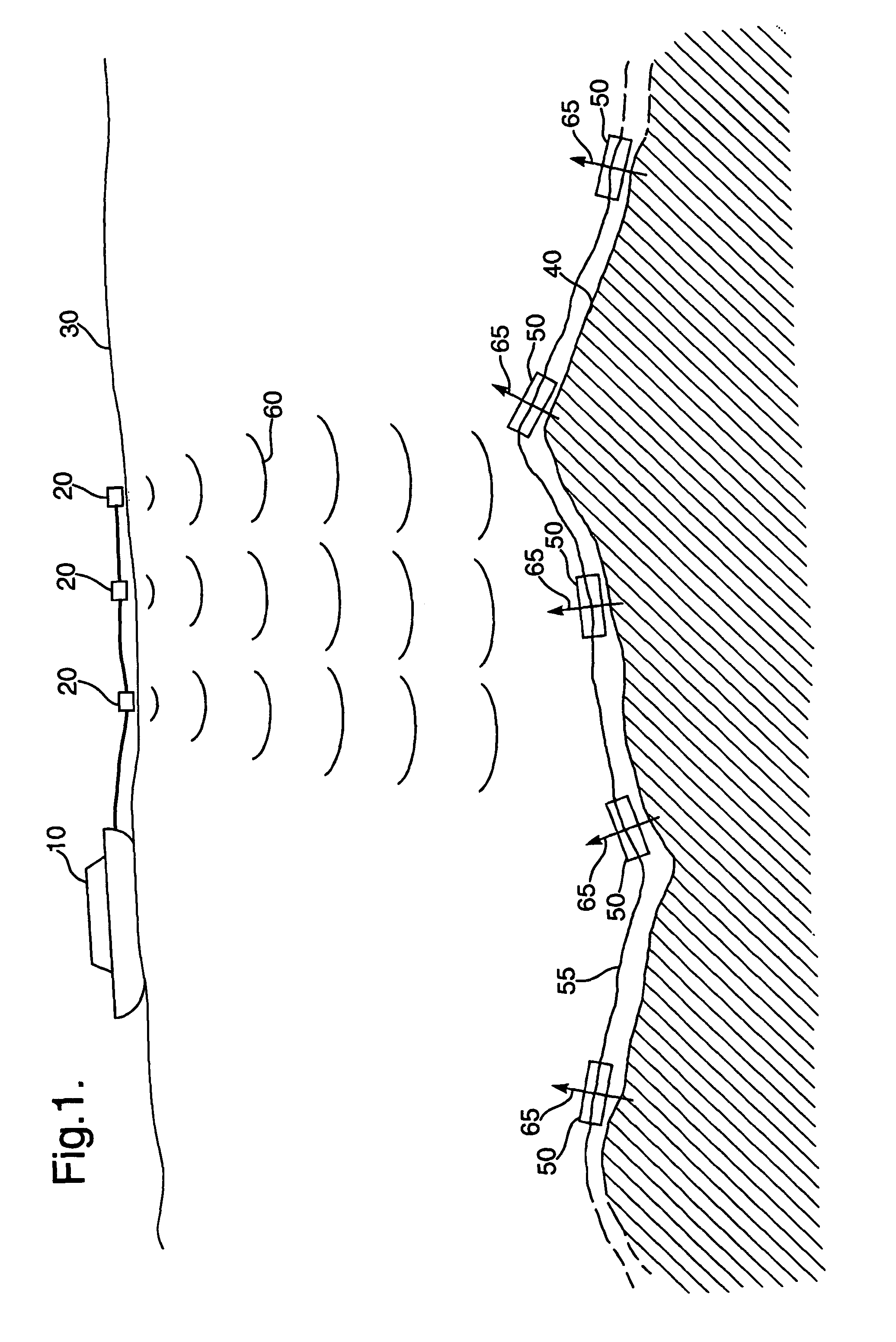
[0047]FIG. 1 is a diagram illustrating a deployment of a fibre optic seabed seismic array in accordance with an embodiment of the present invention. The array consists of a plurality of packages 50 coupled by a fibre optic cable 55. The array is deployed on the seabed 40, and depending on the depth of the seabed 40 below the sea surface 30, this deployment may be performed by divers positioning each package 50 on the seabed, or by the use of submersible vehicles to perform such positioning, or the array may be directly deployed from the surface without assistance at the seabed.

[0048]Attached to one end of the fibre optic cable 55 will be an optical signal source such as a laser for propagating an optical signal along the fibre optic cable 55, and some receive circuitry for detecting the signals returned from the sensors within each of the packages 50. This optical signal source and receive circuitry is not illustrated in FIG. 1, but would typically be located at some convenient loca...


PUM


Abstract

The present invention provides an attitude sensing device and method for determining an attitude of a reference axis of a package containing a fiber optic sensor sensor. The attitude sensing device comprises an electro-mechanical attitude sensor for generating an electrical signal indicative of the attitude sensor, and converter logic for converting the electrical signal into a stimulus signal. A local power source is preferably provided for the electro-mechanical attitude sensor in the converter logic. The stimulus signal is such that the fiber optical sensor is responsive to the stimulus signal to cause a variation in at least one predetermined property of an optical signal transmitted through the fiber optic sensor, the attitude of the reference axis being determinable from the variation of the predetermined property. By this approach, it is possible to use the existing fiber optic sensor within the package, along with the corresponding existing telemetry and multiplexing system, to recover the information from the electro-mechanical attitude sensor.

Description

FIELD OF THE INVENTION[0001]The present invention relates to an attitude sensing device and an attitude sensing method, and in particular to techniques for determining an attitude in three dimensional space of a reference axis of a package containing a fibre optic sensor.DESCRIPTION OF THE PRIOR ART[0002]Fibre optic sensors are becoming a well-established technology for a range of applications, for example geophysical applications. Fibre optic sensors can take a variety of forms. For example fibre optic sensors may be arranged to act as static pressure sensors or static temperature sensors. Additionally, fibre optic sensors have also been developed for measuring dynamic quantities such as acoustic and seismic signals, example of such dynamic fibre optic sensors being fibre optic hydrophones and fibre optic geophones. A hydrophone is a device for the measurement of dynamic pressure in a fluid, whilst a geophone is a device for the measurement of vibration (in practice, this can eithe...

Claims


Application Information

Patent Timeline
Patent Type & Authority Patents(United States)
IPC IPC(8): G01H1/00H04B11/00G01C9/00G01V1/20G01V1/38
CPCG01C9/00G01V1/3835G01V1/20
Inventor NASH, PHILIP JOHNTANNER, MARK ANDREW
Owner OPTASENSE HLDG LTD
Why Eureka
Try Eureka