Light source unit

a technology of light source and light source plate, which is applied in the direction of fixed installation, lighting and heating apparatus, lighting support devices, etc., can solve the problems of increasing cost, high processing cost of etching and so on, and high unit cost of aluminum board, so as to prevent the expansion of uneven intensity distribution, shorten the interval between the reflection plane, and improve the effect of heat radiating properties

Active Publication Date: 2006-04-04
FUJIFILM HLDG CORP +1
View PDF10 Cites 105 Cited by
  • Summary
  • Abstract
  • Description
  • Claims
  • Application Information

AI Technical Summary

Benefits of technology

[0009]In view of the foregoing, it is a primary object of the present invention to provide a light source unit comprising a light-emitting element array in which its heat radiation property is improved without increasing the costs.
[0010]It is a second object of the present invention to provide a light source unit comprising a light-emitting element array in which unevenness of intensity distribution of the array is prevented from being enlarged.
[0015]According to the present invention, it is possible to shorten an interval between the reflection plane and the light-emitting element. Consequently, unevenness of intensity distribution may be prevented from being enlarged. Moreover, since the light-emitting element array is separated from the printed-circuit board, heat radiating properties may be improved without using an expensive printed-circuit board having good heat radiating properties.

Problems solved by technology

However, unit cost of the aluminum board is expensive in comparison with the resinous board.
In addition, processing cost of etching and so forth is high.
Thus, there arises a problem in that the cost increases.
When the interval is broad, there arises a problem in that unevenness of intensity distribution is enlarged in the longitudinal direction (scanning direction).
This problem is caused because the light-emitting element array is merely an aggregation of point sources (light-emitting elements) from a microscopic view, although this array is macroscopically regarded as a linear light source.

Method used


Image

  • Light source unit
  • Light source unit
  • Light source unit

Examples


Embodiment Construction

)

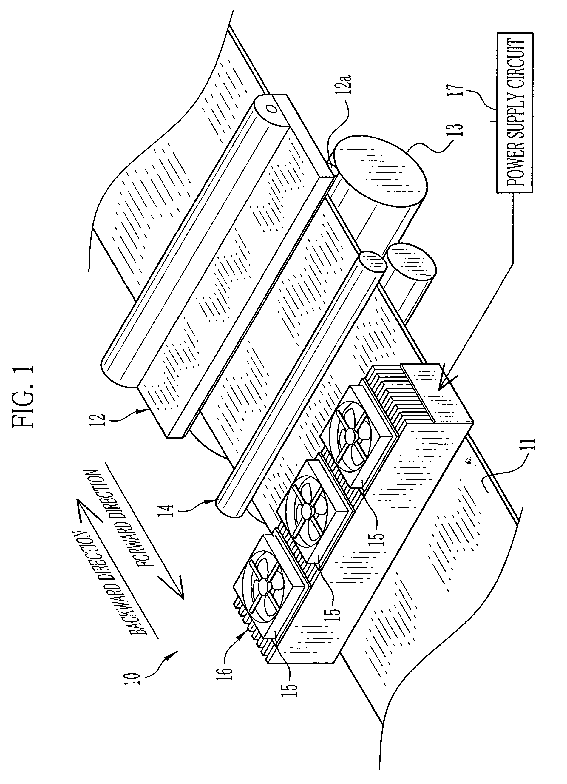
[0030]FIG. 1 shows a color thermal printer 10 in which a light source unit of the present invention is used as a light source for optical fixation. The color thermal printer 10 reciprocates a color thermosensitive recording paper 11 in forward and backward directions. During the reciprocation, it is performed to thermally record a full-color image and to optically fix the recording paper 11 for which thermal recording has been performed.

[0031]As well known, the color thermosensitive recording paper 11 comprises three thermosensitive coloring layers of yellow, magenta and cyan, which are formed on a support in this order from the uppermost layer. As to this recording paper 11, the yellow thermosensitive coloring layer being as the uppermost layer has the highest heat sensitivity, and the cyan thermosensitive coloring layer being as the lowermost layer has the lowest heat sensitivity.

[0032]Each of the yellow and magenta thermosensitive coloring layers has an optical fixation property...


PUM


Abstract

Light-emitting element arrays having aligned LEDs are fixed to a stand integrally formed with a heat sink. An attachment surface of the stand is formed with V-shaped grooves working as reflection planes for improving irradiation efficiency. The arrays are separated from printed-circuit boards to be bonded therewith by wires. The array is placed at the bottom of the groove. The printed-circuit board is placed on a step formed at a wall of the groove. Since the array is separated from the resinous printed-circuit board having inferior heat conductance, high efficiency of heat radiation is obtained. Further, since the array is disposed close to the wall, unevenness of intensity distribution of the LEDs is prevented from being enlarged.

Description

BACKGROUND OF THE INVENTION[0001]1. Field of the Invention[0002]The present invention relates to a light source unit including a plurality of light-emitting elements, which are arranged in line.[0003]2. Description of the Related Art[0004]A light source unit comprising a light-emitting element array is known. In this array, a plurality of light-emitting elements (LED, for instance) are aligned (see Japanese Patent Laid-Open Publication No. 6-225080). For example, the light-emitting element array is constituted such that the light-emitting elements are mounted side by side on a printed-circuit board on which a circuit pattern to be connected to a power source is printed. Electrodes of the respective light-emitting elements are electrically connected to the circuit pattern by wire bonding.[0005]This kind of the light source unit comes into use as an original-illuminating light source of a scanner and a copying machine instead of a linear fluorescent lamp conventionally used, since eve...

Claims


Application Information

Patent Timeline
Patent Type & Authority Patents(United States)
IPC IPC(8): F21V29/00B41J2/44B41J2/45B41J2/455F21S2/00F21S8/04F21V19/00F21V29/02F21Y101/02H01L25/075
CPCB41J2/45F21V29/763H01L25/0753F21V29/004F21V29/76F21V29/677F21Y2101/02F21Y2105/001H01L33/60H01L33/642H01L2224/48091H01L2224/49107H01L2924/3025H01L2924/00014H01L2924/00F21Y2105/10F21Y2115/10F21V29/67
Inventor MIZUYOSHI, AKIRA
Owner FUJIFILM HLDG CORP
Why Eureka
Try Eureka