Method of treating air on board on a vehicle, and a device for use when performing the method

a technology for treating air and vehicles, which is applied in the direction of centrifuges, separation processes, human health protection, etc., to achieve the effect of convenient and inexpensive manufacturing of devices and compact construction

Inactive Publication Date: 2006-04-04
ALFA LAVAL CORP AB +1
View PDF7 Cites 40 Cited by
  • Summary
  • Abstract
  • Description
  • Claims
  • Application Information

AI Technical Summary

Benefits of technology

[0016]The invention also refers to a particular device for use when performing the method described above from treating air on board on a vehicle. The device, which is defined in the following claims, is designed in such a way that gives the device a very compact construction and enables an inexpensive manufacturing of the device. Consequently, the device includes a stationary housing, a centrifuge rotor rotatable in the housing and an electrical motor for rotating the centrifuge rotor around a rotary axis. The centrifuge rotor is journalled in the housing via bearings located merely at two bearing locations at an axial distance from each other, and delimits a plurality of passage for throughflow of compressed air to be clean. The electrical motor includes a stator, which is connected to the housing, and a rotor, which is constituted of a part of the centrifuge rotor and which is journalled in relation to the stator merely via said two bearings. The motor is thus no standard motor with bearings of its own but uses the bearings that the centrifuge rotor needs for its rotation. Thanks to the integration of the centrifuge rotor and the electrical motor, the whole cleaning device becomes compact.

Problems solved by technology

In spite of a repeated reconditioning of the filter material, this has to be replaced after a certain operational time period since it is clogged by oil and solid particles which can not be removed completely by the back-flushing with cleaned compressed air.

Method used


Image

  • Method of treating air on board on a vehicle, and a device for use when performing the method
  • Method of treating air on board on a vehicle, and a device for use when performing the method

Examples


Embodiment Construction

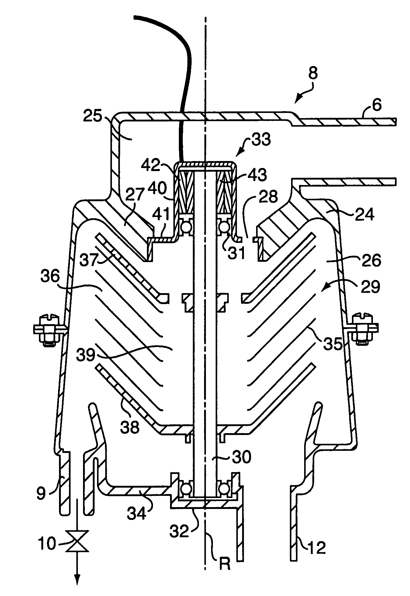
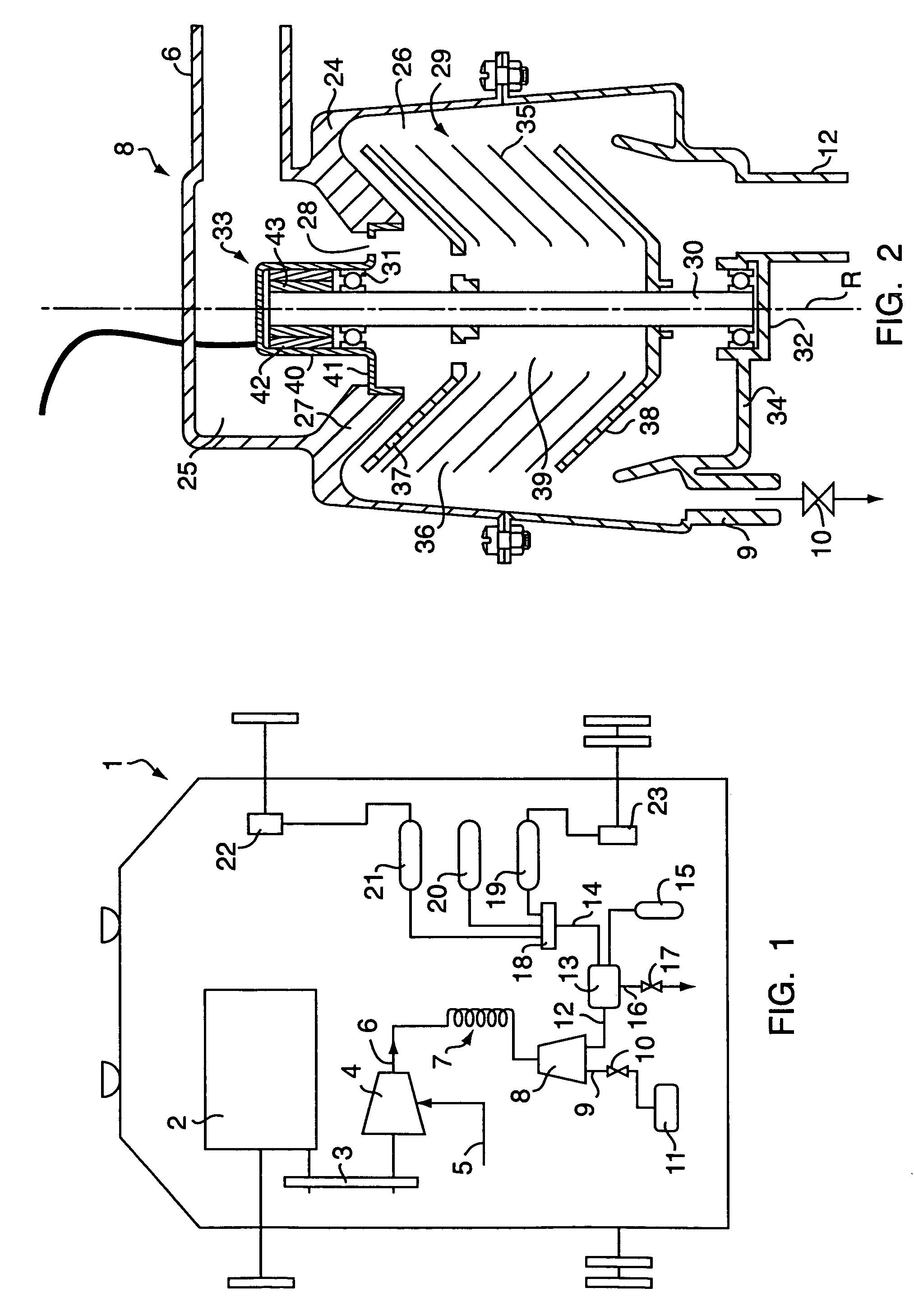
[0020]FIG. 1 illustrates schematically a vehicle 1 having a combustion engine 2 arranged for propelling the vehicle. Via a transmission 3, the engine 1 is arranged to drive an air compressor 4. Air of atmospheric pressure is entering the compressor 4 through a first conduit 5 and compressed air is leaving the compressor through a second conduit 6.

[0021]At its passage through the compressor 4, the air is supplied with particles of oil from the lubrication system (not disclosed) of the compressor. At the same time some steam, which follows the air into the compressor, is condensed to water droplets, which as the oil particles remain suspended in the compressed air. Finally, some oil droplets are converted, as a consequence of a relatively high temperature in the compressor, to solid hydrocarbon particles, which also follow the compressed air out of the compressor.

[0022]The compressed air is brought to flow through a cooler 7, in which a main part of oil vaporised in the air and a part...


PUM

PropertyMeasurementUnit
distanceaaaaaaaaaa
pressureaaaaaaaaaa
shapeaaaaaaaaaa

Abstract

In a vehicle air is compressed for being used in the brake system of the vehicle, for instance. In the compressor, used for the compression, the air is contaminated with oil and solid particles. In order to be relieved from these particles, before the air is conveyed through a drying filter, the compressed is brought to rotation by means of a rotating member in a centrifugal separator. The rotating member may advantageously include a pile of conical separation discs forming flow passages between each other for the compressed air to be cleaned. By means of an efficient cleaning of the compressed air from particles the life time of the drying filter may be increased.

Description

CROSS-REFERENCE TO RELATED APPLICATIONS[0001]This application is entitled to the benefit of and incorporates by reference essential subject matter disclosed in Swedish Patent Application No. 0300410-8 filed on Feb. 17, 2003.BACKGROUND OF THE INVENTION[0002]On board on a vehicle, such as a truck, a bus or a working vehicle, air for use in for instance the brake system and / or the wheel suspension system of the vehicle is compressed. For pressurizing the air a compressor is used, which frequently is lubricated with oil of the same kind that is used for the lubrication of the engine by which the vehicle is driven. The compressor is driven by means of said engine and supplies intermittently, when so needed, compressed air to one or several overpressure containers in the vehicle. From these containers, compressed air is delivered to for instance the brake system of the vehicle when so required.[0003]Compressed air produced in this manner contains suspended particles of oil, water and a pl...

Claims


Application Information

Patent Timeline
Patent Type & Authority Patents(United States)
IPC IPC(8): B01D45/14B01D50/00B04B5/12B60T17/02
CPCB01D45/14B04B5/12B60T17/02Y10S55/17B04B2005/125Y02A50/2351
Inventor OLSSON, MATSPOGEN, MATS-ORJANHALLGREN, INGVARISAKSSON, ROLANDSZEPESSY, STEFAN
Owner ALFA LAVAL CORP AB
Why Eureka
Try Eureka