Connecting adapter for weld electrode

a technology of connecting adapters and weld electrodes, which is applied in the direction of electrode features, mechanical equipment, manufacturing tools, etc., can solve the problems of degradation of electrodes, wear and/or damage of various copper components of typical resistance welding devices, and wear and/or damage of weld electrodes during use, so as to facilitate quick and easy connection of weld electrodes, low cost replacement, and low cost

Inactive Publication Date: 2006-04-04
HONDA GIKEN KOYGO KUBUSHIKI KIASHA
View PDF22 Cites 19 Cited by
  • Summary
  • Abstract
  • Description
  • Claims
  • Application Information

AI Technical Summary

Benefits of technology

[0009]Therefore, as can be discerned from the foregoing discussion, it is desirable to be able to attach a weld electrode to a resistance welding device in such a manner that removal / installation of the electrode can be accomplished in an efficient manner. It is also desirable that the means of attaching the electrode to the welding device be as inexpensive as possible, thereby providing for low cost replacement. The weld electrode connecting adapter of the present invention satisfies this need. The adapter of the present invention functions as a low cost means of facilitating quick and easy connection of a weld electrode to a resistance welding device. More specifically, one end of the adapter of the present invention may be sealably threaded into a tip holder portion of a resistance welding device. The opposite end of the adapter is designed to receive a weld electrode. The adapter is preferably made from copper, but other conductive materials may also be employed for its construction.
[0010]One embodiment of the adapter of the present invention is provided with parallel threads for threading into a corresponding threaded cavity in the tip holder portion of a resistance welding device. The adapter preferably has a passageway extending longitudinally therethrough to allow for the circulation of cooling water to the electrode. An o-ring may be provided in the vicinity of the threaded portion of the adapter to prevent leakage of cooling fluid from around the threads. Preferably, a receiving groove, or channel, is also provided in the receiving cavity of the tip holder to receive the o-ring and to provide a proper seal. The electrode receiving end of the adapter is preferably tapered to receive a like-tapered electrode. The adapter can generally be installed to a tip holder with a common wrench, although it may also be designed to require a specialized installation / removal tool. In certain embodiments, an electrode can be installed to the adapter in the normal fashion—by tapping it into position with a hammer or other acceptable tool.

Problems solved by technology

However, all forms of resistance welding operate to join work pieces by causing the localized heating thereof.
Overheating of the weld electrodes, for example, can be detrimental to the appearance of the work piece surfaces, and can also cause degradation of the electrodes.
Consequently, the various copper components of typical resistance welding devices are prone to wear and / or damage.
For example, weld electrodes wear down during use as a result of heat generated by the welding process, and also due to the force they are required to exert against the work pieces upon which they operate.
Eventually, however, the weld electrode will wear beyond an acceptable limit, and must then be replaced.
As can be surmised from the above description, due to the softness of the copper material, electrode replacement will eventually have a detrimental effect on the condition of the mating components of the resistance welding device.
For example, in the above, former example, repeated removal / installation of connecting adapters or electrodes to / from the cavity in the weld tip holder will eventually lead to the deformation thereof.
Similarly, repeated removal / installation of electrodes to / from the protruding male portion of weld tip holder in the above, latter example, will eventually lead to the deformation thereof, and to possible deformation of a larger portion of the tip holder as a result of repeated impact.
Consequently, such components require periodic replacement.
One problem with known resistance welding devices is that there has been, heretofore, no easy, quick, and inexpensive way to replace such components.
Such a process can require a significant amount of time to accomplish, as the tip holder is typically attached to the gun arm by a number of fasteners.
Further, such a process can be expensive, as in addition to the cost associated with repair or replacement of the tip holder, a plurality of spare tip holders must be kept stocked and available.

Method used


Image

  • Connecting adapter for weld electrode
  • Connecting adapter for weld electrode
  • Connecting adapter for weld electrode

Examples


Embodiment Construction

)

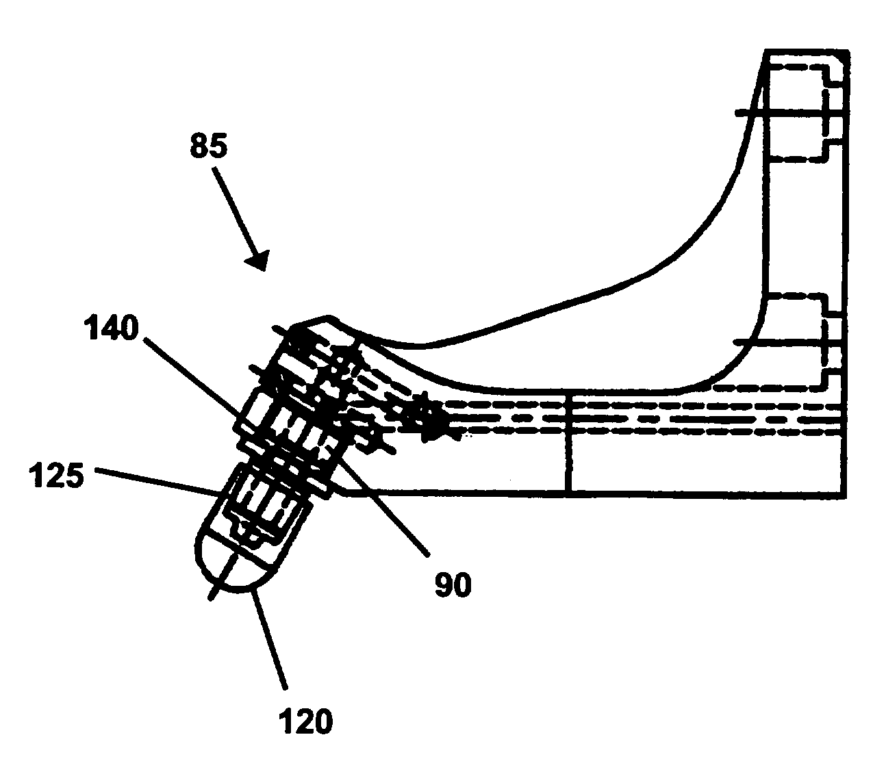
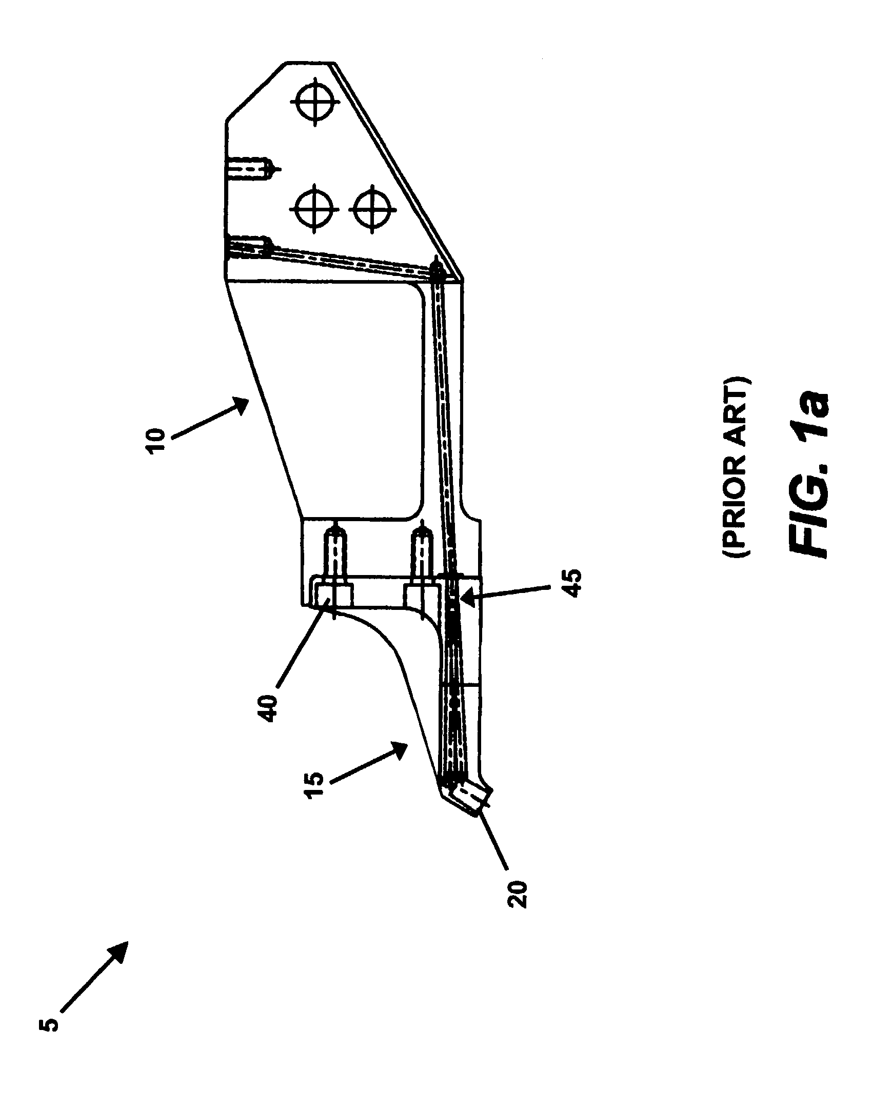
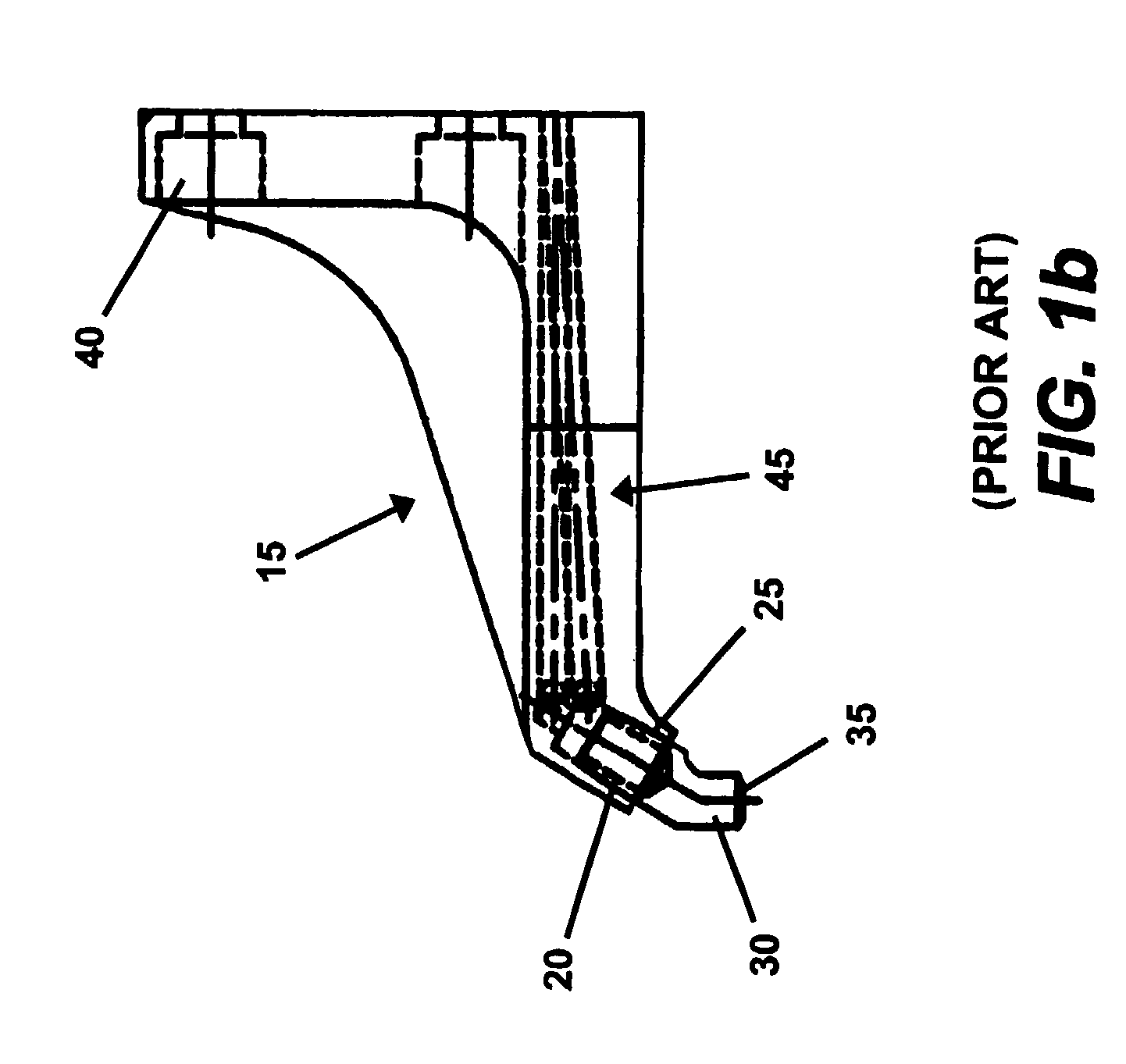
[0021]A portion of a known resistance welding device 5 without, and with a connecting adapter 30 installed thereto, can be observed by reference to FIGS. 1a and 1b, respectively. As can be seen, the visible portion of the welding device 5 includes a gun arm 10, to which is affixed a tip holder 15. The tip holder 15 is provided with a receiving cavity 20. The receiving cavity 20 is designed to receive a shank portion of a specialized electrode or, more commonly, the shank portion 25 of a connecting adapter 30. The receiving cavity 20 and the shank portion 25 of the electrode or connecting adapter 30 are tapered to facilitate their assembly. Generally, the fit of the shank portion 25 into the receiving cavity 20 is a tight force fit, with the malleability of the copper allowing for secure retainment.

[0022]In operation, the connecting adapter 30 is installed to the tip holder 15 by tapping on the adapter until the shank portion 25 thereof is sufficiently driven into the tip holder's r...


PUM

PropertyMeasurementUnit
lengthaaaaaaaaaa
conductiveaaaaaaaaaa
perimeteraaaaaaaaaa

Abstract

An electrically and thermally conductive adapter for connecting a weld electrode to a tip holder portion of a welding device. The adapter has a first, threaded end, for removable engagement with a like-threaded receiving cavity in the tip holder. The threads may be of parallel configuration to minimize damage to the receiving cavity. The adapter has a second, preferably tapered end, for receiving a removable weld electrode. A passageway is preferably provided through the adapter for transporting cooling fluid to the electrode. An o-ring may be retained on the adapter and designed to engage with a groove in the receiving cavity in order to prevent leakage of cooling fluid from around the threads. The adapter is economical to manufacture and may be quickly and easily removed or installed to the tip holder. The adapter reduces damage to the tip holder commonly caused by the repeated changing of electrodes.

Description

BACKGROUND AND SUMMARY OF THE INVENTION[0001]The present invention relates generally to a connecting adapter for connecting a weld electrode to a welding device, particularly a resistance welding device. More specifically, the present invention relates to a one-piece adapter, one end of which may be removably and sealably installed to a tip holder portion of a resistance welding device, while the opposite end is adapted to receive a weld electrode. The adapter is easy to install and remove, and is inexpensive to manufacture. Consequently, the adapter can be easily replaced as it wears.[0002]Resistance welding is a commonly employed technique for joining metallic work pieces via electric current. There are several forms of resistance welding, including spot welding, seam welding, projection welding, and butt welding. However, all forms of resistance welding operate to join work pieces by causing the localized heating thereof. The localized heating is sufficient to produce a molten we...

Claims


Application Information

Patent Timeline
Patent Type & Authority Patents(United States)
IPC IPC(8): B23K11/30
CPCB23K11/314
Inventor PRATT, THOMAS
Owner HONDA GIKEN KOYGO KUBUSHIKI KIASHA
Why Eureka
Try Eureka