Power-line carrier communication apparatus

Active Publication Date: 2006-04-04
PANASONIC CORP
View PDF10 Cites 36 Cited by
  • Summary
  • Abstract
  • Description
  • Claims
  • Application Information

AI Technical Summary

Benefits of technology

[0018]As a consequence, such a power-line carrier communication apparatus can be obtained. That is, even when the guard interval is eliminated which constitutes the factor of deteriorating the transmission speed, data communications can be carried out. While frequency bands used in the data communication

Problems solved by technology

While the frequency band used in the communication is limited in correspondence with the radio laws/regulations of the respective countries, the sufficiently large attenuation amounts may be obtained in the frequency bands used in the existing communication systems without installing the band-block filter which causes the factor of increasing the circuit scale.
While frequency bands used in the data communications are limited in correspondence with the radio laws/regulations of the respective countries, sufficiently large attenuation

Method used


Image

  • Power-line carrier communication apparatus
  • Power-line carrier communication apparatus
  • Power-line carrier communication apparatus

Examples


embodiment mode 1

(Embodiment Mode 1)

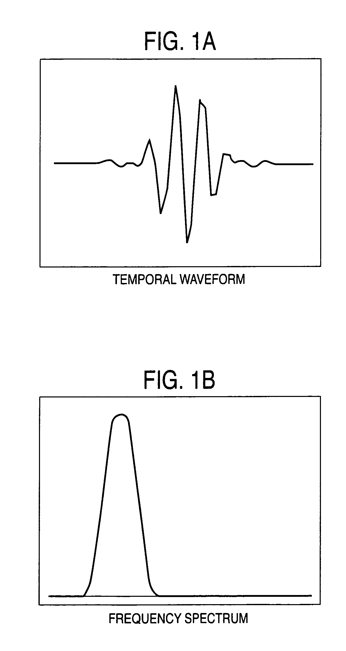
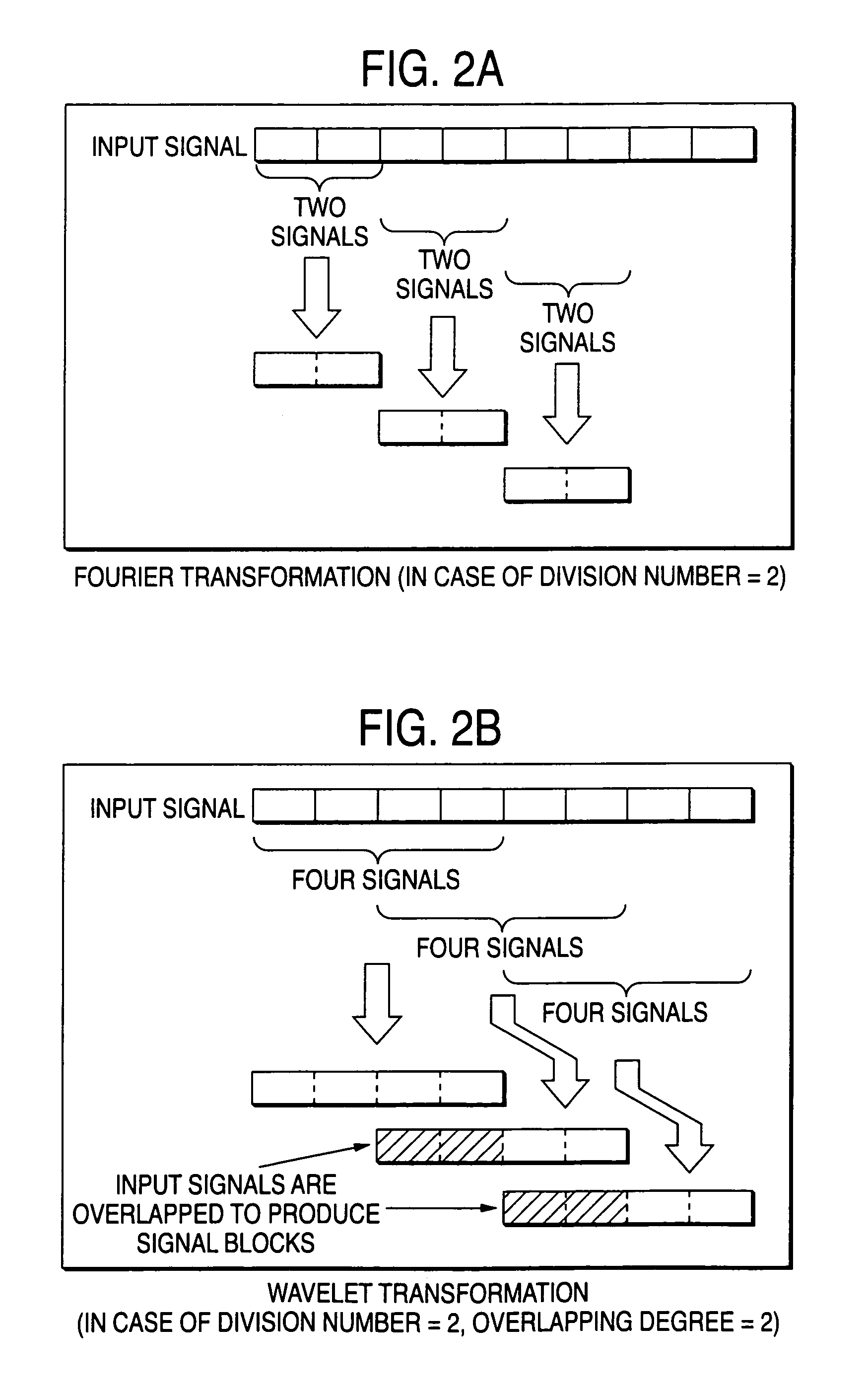
[0051]First, different points of modulating / demodulating operations executed by the Fourier transformation and the wavelet transformation will now be described with reference to FIGS. 1A, 1B, 2A, and 2B. FIG. 1A shows a graph for explaining a conceptional idea as to a temporal waveform of a wavelet, and FIG. 1B indicates a graph for explaining a conceptional idea as to a frequency spectrum of a wavelet. FIG. 2A is an explanatory diagram for explaining a data flow in orthogonal transforming operation, and FIG. 2B is an explanatory diagram for explaining a data flow in overlapped orthogonal transforming operation.

[0052]In the modulating / demodulating operations using the Fourier transformation, a plurality of trigonometric functions which are orthogonally intersected with each other are multiplied by a window function of a rectangular wave to constitute each of sub-carriers. At this time, a frequency characteristic becomes Sinc function (Sinx / x function). On the othe...

embodiment mode 2

(Embodiment Mode 2)

[0063]FIG. 6 is a block diagram for indicating a power-line carrier communication apparatus according to an embodiment mode 2 of the present invention. In this embodiment mode 2, a description is made of such a case that a baseband signal in the embodiment mode 1 is expanded to a band signal in which an arbitrary carrier is set to a center thereof.

[0064]In FIG. 6, reference numeral 101 shows a transmission unit, and reference numeral 111 indicates a reception unit. The transmission unit 101 is provided with a signal point mapping device 102, a wavelet inverse transforming device 103, an SSB (Single SideBand) modulator 107 functioning as a transmitting frequency converter, a D / A converter 104, a transmitting amplifier 105, and a band-pass filter 106. Also, the reception unit 111 is equipped with a band-pass filter 112, an amplification controller 113, an SSB demodulator 117 functioning as a receiving frequency converter, a wavelet transforming device 115, and a sym...

embodiment mode 3

(Embodiment Mode 3)

[0070]FIG. 7 is a block diagram for indicating a power-line carrier communication apparatus 100 according to an embodiment mode 3 of the present invention.

[0071]In FIG. 7, reference numeral 101 shows a transmission unit, and reference numeral 111 indicates a reception unit. The transmission unit 101 is provided with a signal point mapping device 102, a wavelet inverse transforming device 103, a D / a converter 104, a quadrature modulator 108, a transmission amplifier 105, and a band-pass filter 106. Also, the reception unit 111 is equipped with a band-pass filter 112, an amplification controller 113, an A / D converter 114, a quadrature demodulator 118, a wavelet transforming device 115, and a symbol judging device 116. The power-line carrier communication apparatus 100 is arranged by the transmission unit 101, the reception unit 111, a power-line coupling circuit 121, and an overall control unit 122.

[0072]Operations of the power-line carrier communication apparatus 1...


PUM


Abstract

The invention provides a power-line carrier communication apparatus including a transmission unit with a signal point mapping device for mapping a plurality of bit streams produced from transmission data, a wavelet inverse transforming device for modulating the respective sub-carriers by wavelet waveforms which are orthogonal to each other for producing temporal waveform series data, and a D/A converter for converting the temporal waveform series data into an analog temporal waveform series signal; and a reception unit with an A/D converter for obtaining sampling-series waveform data from a power-line communication signal, a wavelet transforming device for wavelet-transforming the sampling-series waveform data into signal point data of the respective sub-carriers, and a symbol judging device for judging bit streams mapped by the signal point mapping device by inverse-mapping a plurality of these signal point data, and for synthesizing the judged bit streams with each other as a reception data series.

Description

BACKGROUND OF THE INVENTION[0001]1. Field of the Invention[0002]The present invention is related to a power-line carrier communication apparatus for performing a data transmission by using a power line.[0003]2. Description of the Related Art[0004]Power-line carrier communication apparatus own a major feature such that in-home communication networks can be immediately established by utilizing as network transmission paths, power lines which have already been installed in the respective homes. However, since these power-line carrier communication apparatus transmit / receive signals by employing such power lines having deteriorated balancing degrees as communication media, high electric power is leaked from these power lines. Also, in frequency bands required for highspeed power-line carrier communications, amateur radio communications and shortwave broadcasting programs have already utilized these frequency bands. As a result, there is a problem of interference caused by these power-li...

Claims


Application Information

Patent Timeline
IPC IPC(8): H04K1/10H04B3/54H04L27/00
CPCH04B3/54H04B3/542H04L27/0004H04L5/0008H04B2203/5416H04L27/2627H04L27/2649H04B3/546
Inventor KODAMA, NOBUTAKAKOGA, HISAOGONDO, TAKAO
Owner PANASONIC CORP
Why Eureka
Try Eureka