Method and system for processing a discrete time input signal where the clock rate of a discrete time output signal is a multiple of the clock rate of input signal samples

a discrete time output and clock rate technology, applied in the field of signal processing, can solve the problems of inability to achieve the effect of accurate signal processing results, computationally expensive and slow signal processing techniques, etc., and achieve the effect of efficient and accurate interpolation techniques and accurate signal processing results

Inactive Publication Date: 2006-04-04
ASML HLDG NV
View PDF9 Cites 2 Cited by
  • Summary
  • Abstract
  • Description
  • Claims
  • Application Information

AI Technical Summary

Benefits of technology

[0009]The present invention is directed to efficient and accurate interpolation techniques. A method of the present invention efficiently processes a discrete time input signal having a plurality of input signal samples that occur at a first clock rate into a discrete time output signal having a second clock rate that is R times the first clock rate. This method includes receiving the input signal and filtering the input signal with an N-taps finite impulse re...

Problems solved by technology

However, signal processing techniques can be computationally expensive and slow.
In addition, processing pla...

Method used


Image

  • Method and system for processing a discrete time input signal where the clock rate of a discrete time output signal is a multiple of the clock rate of input signal samples
  • Method and system for processing a discrete time input signal where the clock rate of a discrete time output signal is a multiple of the clock rate of input signal samples
  • Method and system for processing a discrete time input signal where the clock rate of a discrete time output signal is a multiple of the clock rate of input signal samples

Examples


Embodiment Construction

I. Operational Environment

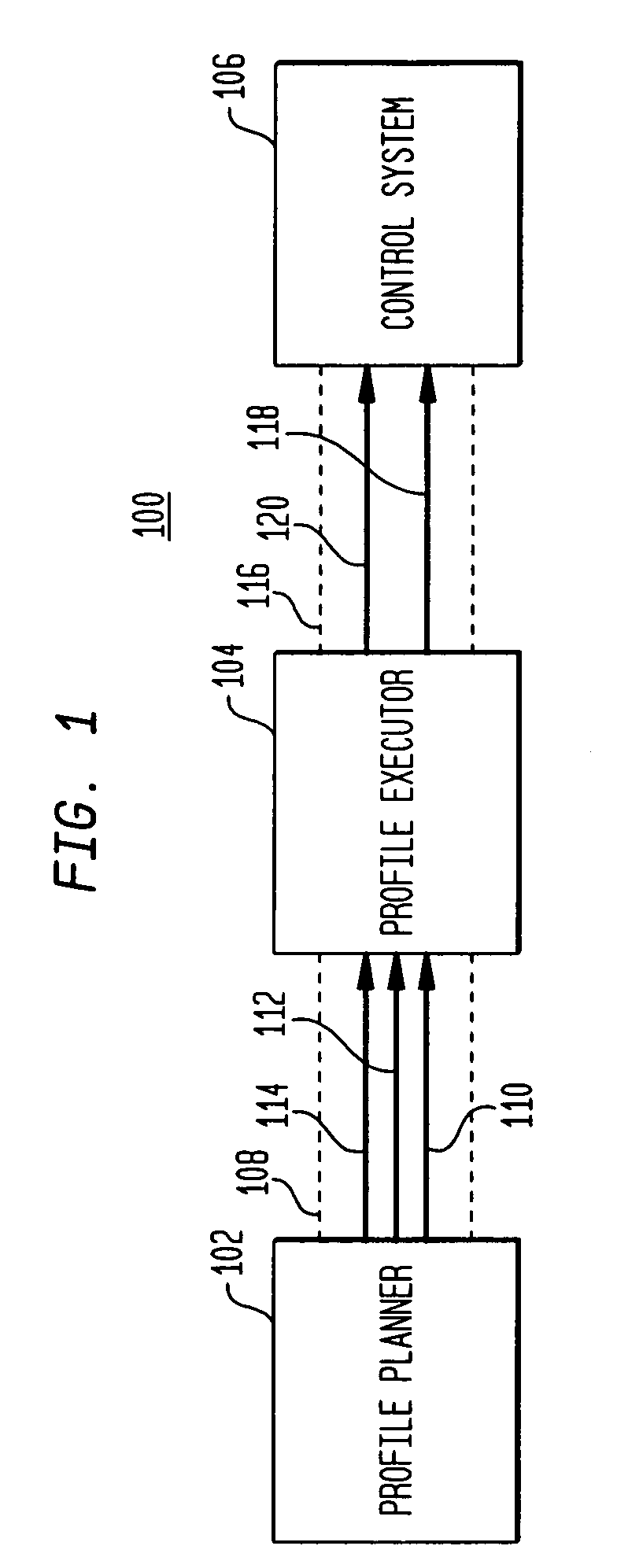
[0025]Before describing the invention in detail, it is useful to describe an example environment in which the invention can be implemented. As the invention is directed to signal processing techniques, it is particularly useful in photolithography applications, such as profile planning and the command and control of photolithography scanning processes. FIG. 1 illustrates such an environment.

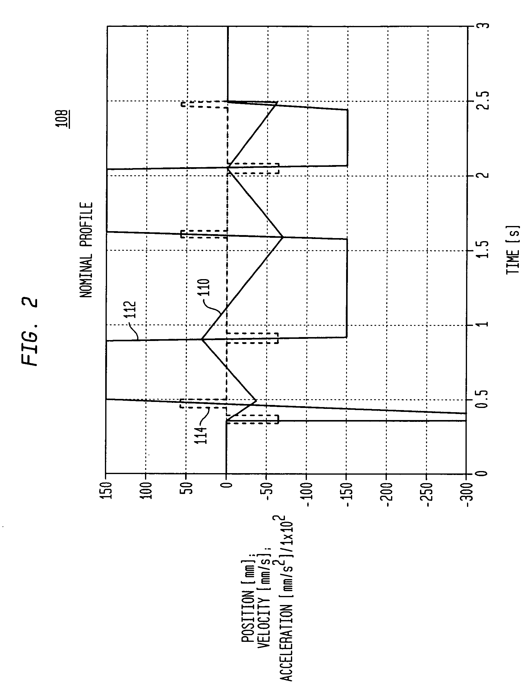
[0026]FIG. 1 is a block diagram of an exemplary operational environment 100. Operational environment 100 includes a profile planner 102, a profile executor 104, and a control system 106. Profile planner 102 designs device trajectories in accordance with user-specified requirements. This design process results in the generation of a state signal set 108 that defines a trajectory for a device, such as a scanning trajectory for a substrate stage or a reticle stage in a photolithography tool. Profile planner 102 is implemented as a computer program product that is executed b...


PUM


Abstract

A method and system of efficiently processing a discrete time input signal having a plurality of input signal samples that occur at a first clock rate into a discrete time output signal having a second clock rate that is R times the first clock rate is presented. The method includes receiving the input signal and filtering the input signal with an N-taps finite impulse response (FIR) filter having N filter coefficients. The method reduces the number of required operations and reduces computational errors in the filtering and interpolation of discrete input signals.

Description

CROSS REFERENCE TO RELATED APPLICATIONS[0001]This application is a Divisional patent application of U.S. patent application Ser. No. 09 / 757,622, filed Jan. 11, 2001, now U.S. Pat. No. 6,766,339 B2, issued Jul. 20, 2004, which is hereby incorporated herein by reference in its entirety.[0002]This application is related to U.S. patent application Ser. No. 10 / 806,325, filed Mar. 23, 2004, entitled “Method and System for Efficient and Accurate Processing of a Discrete Time Input Signal,” having the same inventor, which is hereby incorporated herein by reference in its entirety.BACKGROUND OF THE INVENTION[0003]1. Field of the Invention[0004]The present invention relates to signal processing. More particularly, the present invention relates to efficient and accurate filtering and interpolation techniques for discrete time input signals.[0005]2. Related Art[0006]Many industrial processes involve motion along trajectories that are defined by precise positions at specific times. Photolithogra...

Claims


Application Information

Patent Timeline
IPC IPC(8): G06F17/10G03F7/20H01L21/027H03H17/00H03H17/06
CPCG03F7/70725H03H17/0657H03H17/0621H03H17/0235H03H17/06
Inventor WIENER, ROBERTO B.
Owner ASML HLDG NV
Why Eureka
Try Eureka